A fundamental property of a static magnetic field is that, unlike an electrostatic field, it is not conservative. A conservative vector field is one whose line integral between two end points is the same regardless of the path chosen. Magnetic fields do not have such a property. Instead, there is a relationship between the magnetic field and its source, electric current. It is expressed in terms of the line integral of and is known as Ampère’s law. This law can also be derived directly from the Biot-Savart law. We now consider that derivation for the special case of an infinite, straight wire.
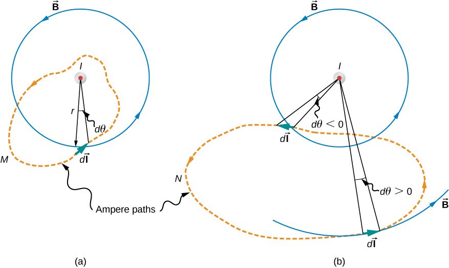
Figure 12.14 shows an arbitrary plane perpendicular to an infinite, straight wire whose current I is directed out of the page. The magnetic field lines are circles directed counterclockwise and centered on the wire. To begin, let’s consider over the closed paths M and N. Notice that one path (M) encloses the wire, whereas the other (N) does not. Since the field lines are circular, is the product of B and the projection of dl onto the circle passing through If the radius of this particular circle is r, the projection is and
Figure 12.14The current I of a long, straight wire is directed out of the page. The integral equals and 0, respectively, for paths M and N.
Path N, on the other hand, circulates through both positive (counterclockwise) and negative (clockwise) (see Figure 12.14), and since it is closed, Thus for path N,
The extension of this result to the general case is Ampère’s law.
To determine whether a specific current I is positive or negative, curl the fingers of your right hand in the direction of the path of integration, as shown in Figure 12.14. If I passes through S in the same direction as your extended thumb, I is positive; if I passes through S in the direction opposite to your extended thumb, it is negative.
Summary
The magnetic field created by current following any path is the sum (or integral) of the fields due to segments along the path (magnitude and direction as for a straight wire), resulting in a general relationship between current and field known as Ampère’s law.
Ampère’s law can be used to determine the magnetic field from a thin wire or thick wire by a geometrically convenient path of integration. The results are consistent with the Biot-Savart law.
Conceptual Questions
Is Ampère’s law valid for all closed paths? Why isn’t it normally useful for calculating a magnetic field?
Ampère’s law is valid for all closed paths, but it is not useful for calculating fields when the magnetic field produced lacks symmetry that can be exploited by a suitable choice of path.
Problems
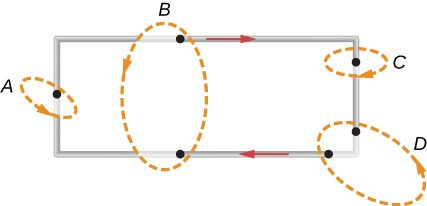
A current I flows around the rectangular loop shown in the accompanying figure. Evaluate for the paths A, B, C, and D.
a. b. 0; c. d. 0
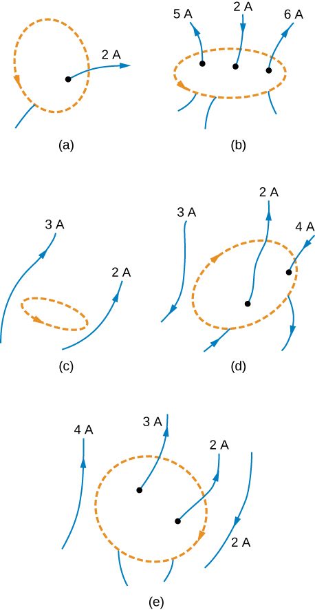
Evaluate for each of the cases shown in the accompanying figure.
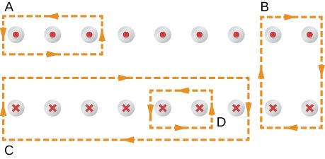
The coil whose lengthwise cross section is shown in the accompanying figure carries a current I and has N evenly spaced turns distributed along the length l. Evaluate for the paths indicated.
a. b. 0; c. d.
A superconducting wire of diameter 0.25 cm carries a current of 1000 A. What is the magnetic field just outside the wire?
A long, straight wire of radius R carries a current I that is distributed uniformly over the cross-section of the wire. At what distance from the axis of the wire is the magnitude of the magnetic field a maximum?
at the radius R
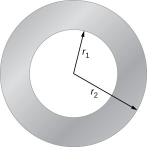
The accompanying figure shows a cross-section of a long, hollow, cylindrical conductor of inner radius and outer radius A 50-A current distributed uniformly over the cross-section flows into the page. Calculate the magnetic field at
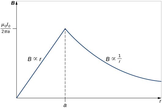
A long, solid, cylindrical conductor of radius 3.0 cm carries a current of 50 A distributed uniformly over its cross-section. Plot the magnetic field as a function of the radial distance r from the center of the conductor.
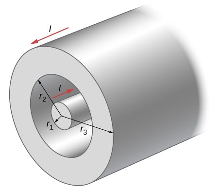
A portion of a long, cylindrical coaxial cable is shown in the accompanying figure. A current I flows down the center conductor, and this current is returned in the outer conductor. Determine the magnetic field in the regions (a) (b) (c) and (d) Assume that the current is distributed uniformly over the cross sections of the two parts of the cable.
Adapted from University Physics Volume 2 by OpenStax (openstax.org), licensed under CC BY-NC-SA 4.0. Changes were made. License: CC-BY-NC-SA-4.0.
These eBooks are a prerelease and are not yet certified conformant with WCAG 2.1 AA or ADA Title II. Every page is built against an automated accessibility gate, and the published editions will meet ADA Title II requirements when they release in late September 2026. If something is unusable, please tell us.