We have seen that mass produces a gravitational field and also interacts with that field. Charge produces an electric field and also interacts with that field. Since moving charge (that is, current) interacts with a magnetic field, we might expect that it also creates that field—and it does.
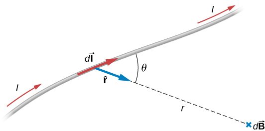
The equation used to calculate the magnetic field produced by a current is known as the Biot-Savart law. It is an empirical law named in honor of two scientists who investigated the interaction between a straight, current-carrying wire and a permanent magnet. This law enables us to calculate the magnitude and direction of the magnetic field produced by a current in a wire. The Biot-Savart law states that at any point P (Figure 12.2), the magnetic field due to an element of a current-carrying wire is given by
Figure 12.2A current element produces a magnetic field at point P given by the Biot-Savart law.
The constant is known as the permeability of free space and is exactly
in the SI system. The infinitesimal wire segment is in the same direction as the current I (assumed positive), r is the distance from to P and is a unit vector that points from to P, as shown in the figure.
The direction of is determined by applying the right-hand rule to the vector product The magnitude of is
(12.3)
where is the angle between and Notice that if then The field produced by a current element has no component parallel to
The magnetic field due to a finite length of current-carrying wire is found by integrating Equation 12.3 along the wire, giving us the usual form of the Biot-Savart law.
Since this is a vector integral, contributions from different current elements may not point in the same direction. Consequently, the integral is often difficult to evaluate, even for fairly simple geometries. The following strategy may be helpful.
Summary
The magnetic field created by a current-carrying wire is found by the Biot-Savart law.
The current element produces a magnetic field a distance r away.
Conceptual Questions
For calculating magnetic fields, what are the advantages and disadvantages of the Biot-Savart law?
Biot-Savart law’s advantage is that it works with any magnetic field produced by a current loop. The disadvantage is that it can take a long time.
Describe the magnetic field due to the current in two wires connected to the two terminals of a source of emf and twisted tightly around each other.
How can you decide if a wire is infinite?
If you were to go to the start of a line segment and calculate the angle to be approximately , the wire can be considered infinite. This judgment is based also on the precision you need in the result.
Identical currents are carried in two circular loops; however, one loop has twice the diameter as the other loop. Compare the magnetic fields created by the loops at the center of each loop.
Problems
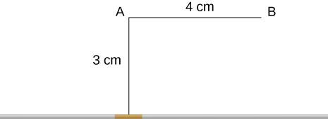
A 10-A current flows through the wire shown. What is the magnitude of the magnetic field due to a 0.5-mm segment of wire as measured at (a) point A and (b) point B?
Ten amps flow through a square loop where each side is 20 cm in length. At each corner of the loop is a 0.01-cm segment that connects the longer wires as shown. Calculate the magnitude of the magnetic field at the center of the loop.
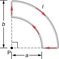
What is the magnetic field at P due to the current I in the wire shown?
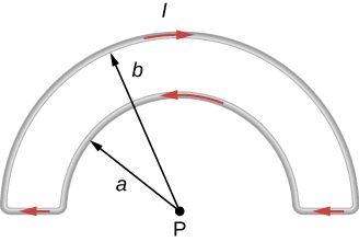
The accompanying figure shows a current loop consisting of two concentric circular arcs and two perpendicular radial lines. Determine the magnetic field at point P.
out of the page
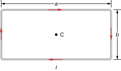
Find the magnetic field at the center C of the rectangular loop of wire shown in the accompanying figure.
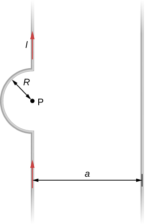
Two long wires, one of which has a semicircular bend of radius R, are positioned as shown in the accompanying figure. If both wires carry a current I, how far apart must their parallel sections be so that the net magnetic field at P is zero? Does the current in the straight wire flow up or down?
; the current in the wire to the right must flow up the page.
Adapted from University Physics Volume 2 by OpenStax (openstax.org), licensed under CC BY-NC-SA 4.0. Changes were made. License: CC-BY-NC-SA-4.0.
These eBooks are a prerelease and are not yet certified conformant with WCAG 2.1 AA or ADA Title II. Every page is built against an automated accessibility gate, and the published editions will meet ADA Title II requirements when they release in late September 2026. If something is unusable, please tell us.