
10.5 Calculating Moments of Inertia
In the preceding section, we defined the moment of inertia but did not show how to calculate it. In this section, we show how to calculate the moment of inertia for several standard types of objects, as well as how to use known moments of inertia to find the moment of inertia for a shifted axis or for a compound object. This section is very useful for seeing how to apply a general equation to complex objects (a skill that is critical for more advanced physics and engineering courses).
Moment of Inertia
We defined the moment of inertia I of an object to be for all the point masses that make up the object. Because r is the distance to the axis of rotation from each piece of mass that makes up the object, the moment of inertia for any object depends on the chosen axis. To see this, let’s take a simple example of two masses at the end of a massless (negligibly small mass) rod (Figure 10.23) and calculate the moment of inertia about two different axes. In this case, the summation over the masses is simple because the two masses at the end of the barbell can be approximated as point masses, and the sum therefore has only two terms.
In the case with the axis in the center of the barbell, each of the two masses m is a distance R away from the axis, giving a moment of inertia of
In the case with the axis at the end of the barbell—passing through one of the masses—the moment of inertia is
From this result, we can conclude that it is twice as hard to rotate the barbell about the end than about its center.
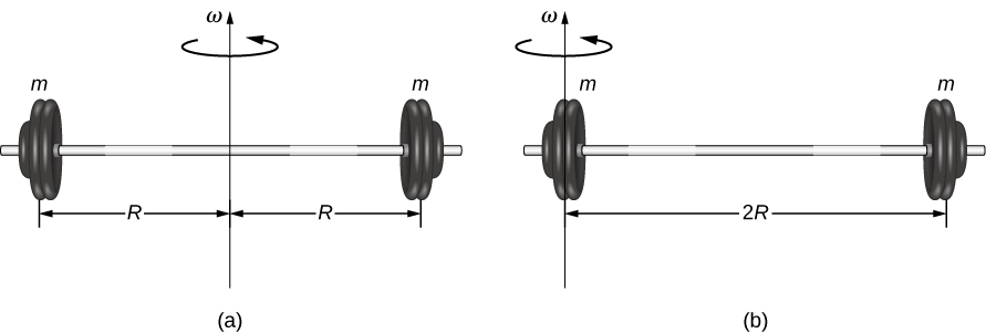
In this example, we had two point masses and the sum was simple to calculate. However, to deal with objects that are not point-like, we need to think carefully about each of the terms in the equation. The equation asks us to sum over each ‘piece of mass’ a certain distance from the axis of rotation. But what exactly does each ‘piece of mass’ mean? Recall that in our derivation of this equation, each piece of mass had the same magnitude of velocity, which means the whole piece had to have a single distance r to the axis of rotation. However, this is not possible unless we take an infinitesimally small piece of mass dm, as shown in Figure 10.24.
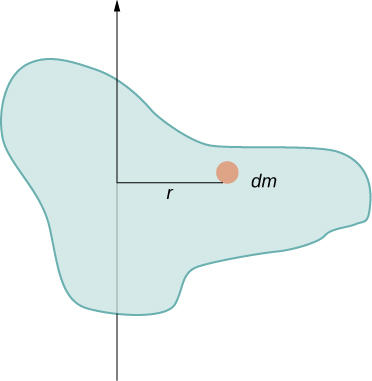
The need to use an infinitesimally small piece of mass dm suggests that we can write the moment of inertia by evaluating an integral over infinitesimal masses rather than doing a discrete sum over finite masses:
This, in fact, is the form we need to generalize the equation for complex shapes. It is best to work out specific examples in detail to get a feel for how to calculate the moment of inertia for specific shapes. This is the focus of most of the rest of this section.
A uniform thin rod with an axis through the center
Consider a uniform (density and shape) thin rod of mass M and length L as shown in Figure 10.25. We want a thin rod so that we can assume the cross-sectional area of the rod is small and the rod can be thought of as a string of masses along a one-dimensional straight line. In this example, the axis of rotation is perpendicular to the rod and passes through the midpoint for simplicity. Our task is to calculate the moment of inertia about this axis. We orient the axes so that the z-axis is the axis of rotation and the x-axis passes through the length of the rod, as shown in the figure. This is a convenient choice because we can then integrate along the x-axis.
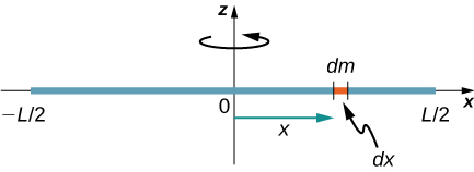
We define dm to be a small element of mass making up the rod. The moment of inertia integral is an integral over the mass distribution. However, we know how to integrate over space, not over mass. We therefore need to find a way to relate mass to spatial variables. We do this using the linear mass density of the object, which is the mass per unit length. Since the mass density of this object is uniform, we can write
If we take the differential of each side of this equation, we find
since is constant. We chose to orient the rod along the x-axis for convenience—this is where that choice becomes very helpful. Note that a piece of the rod dl lies completely along the x-axis and has a length dx; in fact, in this situation. We can therefore write , giving us an integration variable that we know how to deal with. The distance of each piece of mass dm from the axis is given by the variable x, as shown in the figure. Putting this all together, we obtain
The last step is to be careful about our limits of integration. The rod extends from to , since the axis is in the middle of the rod at . This gives us
Next, we calculate the moment of inertia for the same uniform thin rod but with a different axis choice so we can compare the results. We would expect the moment of inertia to be smaller about an axis through the center of mass than the endpoint axis, just as it was for the barbell example at the start of this section. This happens because more mass is distributed farther from the axis of rotation.
A uniform thin rod with axis at the end
Now consider the same uniform thin rod of mass M and length L, but this time we move the axis of rotation to the end of the rod. We wish to find the moment of inertia about this new axis (Figure 10.26). The quantity dm is again defined to be a small element of mass making up the rod. Just as before, we obtain
However, this time we have different limits of integration. The rod extends from to , since the axis is at the end of the rod at . Therefore we find
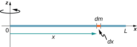
Note the rotational inertia of the rod about its endpoint is larger than the rotational inertia about its center (consistent with the barbell example) by a factor of four.
The Parallel-Axis Theorem
The similarity between the process of finding the moment of inertia of a rod about an axis through its middle and about an axis through its end is striking, and suggests that there might be a simpler method for determining the moment of inertia for a rod about any axis parallel to the axis through the center of mass. Such an axis is called a parallel axis. There is a theorem for this, called the parallel-axis theorem, which we state here but do not derive in this text.
Let’s apply this to the rod examples solved above:
This result agrees with our more lengthy calculation from above. This is a useful equation that we apply in some of the examples and problems.
A uniform thin disk about an axis through the center
Integrating to find the moment of inertia of a two-dimensional object is a little bit trickier, but one shape is commonly done at this level of study—a uniform thin disk about an axis through its center (Figure 10.27).
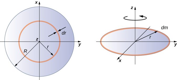
Since the disk is thin, we can take the mass as distributed entirely in the xy-plane. We again start with the relationship for the surface mass density, which is the mass per unit surface area. Since it is uniform, the surface mass density is constant:
Now we use a simplification for the area. The area can be thought of as made up of a series of thin rings, where each ring is a mass increment dm of radius r equidistant from the axis, as shown in part (b) of the figure. The infinitesimal area of each ring dA is therefore given by the length of each ring () times the infinitesimal width of each ring dr:
The full area of the disk is then made up from adding all the thin rings with a radius range from 0 to R. This radius range then becomes our limits of integration for dr, that is, we integrate from to . Putting this all together, we have
Note that this agrees with the value given in Figure 10.20.
Calculating the moment of inertia for compound objects
Now consider a compound object such as that in Figure 10.28, which depicts a thin disk at the end of a thin rod. This cannot be easily integrated to find the moment of inertia because it is not a uniformly shaped object. However, if we go back to the initial definition of moment of inertia as a summation, we can reason that a compound object’s moment of inertia can be found from the sum of each part of the object:
It is important to note that the moments of inertia of the objects in Equation 10.21 are about a common axis. In the case of this object, that would be a rod of length L rotating about its end, and a thin disk of radius R rotating about an axis shifted off of the center by a distance , where R is the radius of the disk. Let’s define the mass of the rod to be and the mass of the disk to be
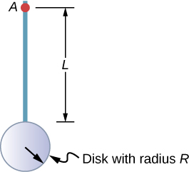
The moment of inertia of the rod is simply , but we have to use the parallel-axis theorem to find the moment of inertia of the disk about the axis shown. The moment of inertia of the disk about its center is and we apply the parallel-axis theorem to find
Adding the moment of inertia of the rod plus the moment of inertia of the disk with a shifted axis of rotation, we find the moment of inertia for the compound object to be
Applying moment of inertia calculations to solve problems
Now let’s examine some practical applications of moment of inertia calculations.
Summary
- Moments of inertia can be found by summing or integrating over every ‘piece of mass’ that makes up an object, multiplied by the square of the distance of each ‘piece of mass’ to the axis. In integral form the moment of inertia is .
- Moment of inertia is larger when an object’s mass is farther from the axis of rotation.
- It is possible to find the moment of inertia of an object about a new axis of rotation once it is known for a parallel axis. This is called the parallel axis theorem given by , where d is the distance from the initial axis to the parallel axis.
- Moment of inertia for a compound object is simply the sum of the moments of inertia for each individual object that makes up the compound object.
Conceptual Questions
If a child walks toward the center of a merry-go-round, does the moment of inertia increase or decrease?
A discus thrower rotates with a discus in his hand before letting it go. (a) How does his moment of inertia change after releasing the discus? (b) What would be a good approximation to use in calculating the moment of inertia of the discus thrower and discus?
a. It decreases. b. The arms could be approximated with rods and the discus with a disk. The torso is near the axis of rotation so it doesn’t contribute much to the moment of inertia.
Does increasing the number of blades on a propeller increase or decrease its moment of inertia, and why?
The moment of inertia of a long rod spun around an axis through one end perpendicular to its length is . Why is this moment of inertia greater than it would be if you spun a point mass m at the location of the center of mass of the rod (at L/2) (that would be )?
Because the moment of inertia varies as the square of the distance to the axis of rotation. The mass of the rod located at distances greater than L/2 would provide the larger contribution to make its moment of inertia greater than the point mass at L/2.
Why is the moment of inertia of a hoop that has a mass M and a radius R greater than the moment of inertia of a disk that has the same mass and radius?
Problems
While punting a football, a kicker rotates their leg about the hip joint. The moment of inertia of the leg is and its rotational kinetic energy is 175 J. (a) What is the angular velocity of the leg? (b) What is the velocity of tip of the punter’s shoe if it is 1.05 m from the hip joint?
Using the parallel axis theorem, what is the moment of inertia of the rod of mass m about the axis shown below?
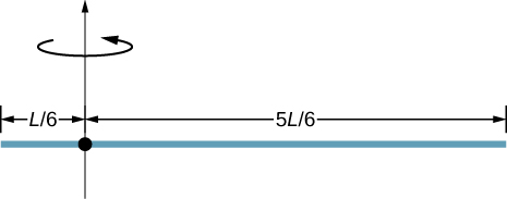
Find the moment of inertia of the rod in the previous problem by direct integration.
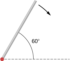
A uniform rod of mass 1.0 kg and length 2.0 m is free to rotate about one end (see the following figure). If the rod is released from rest at an angle of with respect to the horizontal, what is the speed of the tip of the rod as it passes the horizontal position?
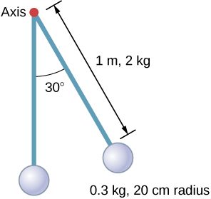
A pendulum consists of a rod of mass 2 kg and length 1 m with a solid sphere at one end with mass 0.3 kg and radius 20 cm (see the following figure). If the pendulum is released from rest at an angle of , what is the angular velocity at the lowest point?
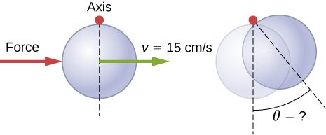
A solid sphere of radius 10 cm is allowed to rotate freely about an axis. The sphere is given a sharp blow so that its center of mass starts from the position shown in the following figure with speed 15 cm/s. What is the maximum angle that the diameter makes with the vertical?
Calculate the moment of inertia by direct integration of a thin rod of mass M and length L about an axis through the rod at L/3, as shown below. Check your answer with the parallel-axis theorem.

Adapted from University Physics Volume 1 by OpenStax (openstax.org), licensed under CC BY-NC-SA 4.0. Changes were made. License: CC-BY-NC-SA-4.0.