
14.5 Oscillations in an LC Circuit
It is worth noting that both capacitors and inductors store energy, in their electric and magnetic fields, respectively. A circuit containing both an inductor (L) and a capacitor (C) can oscillate without a source of emf by shifting the energy stored in the circuit between the electric and magnetic fields. Thus, the concepts we develop in this section are directly applicable to the exchange of energy between the electric and magnetic fields in electromagnetic waves, or light. We start with an idealized circuit of zero resistance that contains an inductor and a capacitor, an LC circuit.
An LC circuit is shown in Figure 14.16. If the capacitor contains a charge before the switch is closed, then all the energy of the circuit is initially stored in the electric field of the capacitor (Figure 14.16(a)). This energy is
When the switch is closed, the capacitor begins to discharge, producing a current in the circuit. The current, in turn, creates a magnetic field in the inductor. The net effect of this process is a transfer of energy from the capacitor, with its diminishing electric field, to the inductor, with its increasing magnetic field.
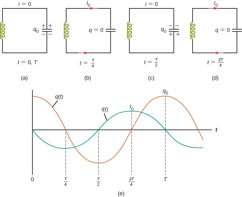
In Figure 14.16(b), the capacitor is completely discharged and all the energy is stored in the magnetic field of the inductor. At this instant, the current is at its maximum value and the energy in the inductor is
Since there is no resistance in the circuit, no energy is lost through Joule heating; thus, the maximum energy stored in the capacitor is equal to the maximum energy stored at a later time in the inductor:
At an arbitrary time when the capacitor charge is q(t) and the current is i(t), the total energy U in the circuit is given by
Because there is no energy dissipation,
After reaching its maximum the current i(t) continues to transport charge between the capacitor plates, thereby recharging the capacitor. Since the inductor resists a change in current, current continues to flow, even though the capacitor is discharged. This continued current causes the capacitor to charge with opposite polarity. The electric field of the capacitor increases while the magnetic field of the inductor diminishes, and the overall effect is a transfer of energy from the inductor back to the capacitor. From the law of energy conservation, the maximum charge that the capacitor re-acquires is However, as Figure 14.16(c) shows, the capacitor plates are charged opposite to what they were initially.
When fully charged, the capacitor once again transfers its energy to the inductor until it is again completely discharged, as shown in Figure 14.16(d). Then, in the last part of this cyclic process, energy flows back to the capacitor, and the initial state of the circuit is restored.
We have followed the circuit through one complete cycle. Its electromagnetic oscillations are analogous to the mechanical oscillations of a mass at the end of a spring. In this latter case, energy is transferred back and forth between the mass, which has kinetic energy , and the spring, which has potential energy . With the absence of friction in the mass-spring system, the oscillations would continue indefinitely. Similarly, the oscillations of an LC circuit with no resistance would continue forever if undisturbed; however, this ideal zero-resistance LC circuit is not practical, and any LC circuit will have at least a small resistance, which will radiate and lose energy over time.
The frequency of the oscillations in a resistance-free LC circuit may be found by analogy with the mass-spring system. For the circuit, , the total electromagnetic energy U is
For the mass-spring system, , the total mechanical energy E is
The equivalence of the two systems is clear. To go from the mechanical to the electromagnetic system, we simply replace m by L, v by i, k by 1/C, and x by q. Now x(t) is given by
where Hence, the charge on the capacitor in an LC circuit is given by
where the angular frequency of the oscillations in the circuit is
Finally, the current in the LC circuit is found by taking the time derivative of q(t):
The time variations of q and I are shown in Figure 14.16(e) for .
Summary
- The energy transferred in an oscillatory manner between the capacitor and inductor in an LC circuit occurs at an angular frequency .
- The charge and current in the circuit are given by
Conceptual Questions
Do Kirchhoff’s rules apply to circuits that contain inductors and capacitors?
yes
Can a circuit element have both capacitance and inductance?
In an LC circuit, what determines the frequency and the amplitude of the energy oscillations in either the inductor or capacitor?
The amplitude of energy oscillations depend on the initial energy of the system. The frequency in a LC circuit depends on the values of inductance and capacitance.
Problems
A 5000-pF capacitor is charged to 100 V and then quickly connected to an 80-mH inductor. Determine (a) the maximum energy stored in the magnetic field of the inductor, (b) the peak value of the current, and (c) the frequency of oscillation of the circuit.
The self-inductance and capacitance of an LC circuit are 0.20 mH and 5.0 pF. What is the angular frequency at which the circuit oscillates?
What is the self-inductance of an LC circuit that oscillates at 60 Hz when the capacitance is ?
In an oscillating LC circuit, the maximum charge on the capacitor is and the maximum current through the inductor is 8.0 mA. (a) What is the period of the oscillations? (b) How much time elapses between an instant when the capacitor is uncharged and the next instant when it is fully charged?
a. ; b.
The self-inductance and capacitance of an oscillating LC circuit are respectively. (a) What is the frequency of the oscillations? (b) If the maximum potential difference between the plates of the capacitor is 50 V, what is the maximum current in the circuit?
In an oscillating LC circuit, the maximum charge on the capacitor is . Determine the charge on the capacitor and the current through the inductor when energy is shared equally between the electric and magnetic fields. Express your answer in terms of , L, and C.
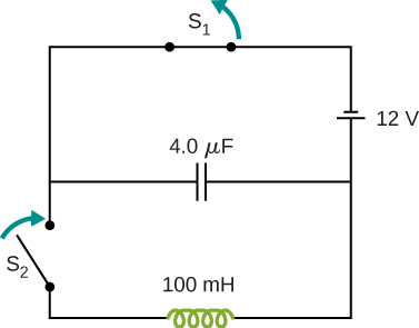
In the circuit shown below, is opened and is closed simultaneously. Determine (a) the frequency of the resulting oscillations, (b) the maximum charge on the capacitor, (c) the maximum current through the inductor, and (d) the electromagnetic energy of the oscillating circuit.
An LC circuit in an AM tuner (in a car stereo) uses a coil with an inductance of 2.5 mH and a variable capacitor. If the natural frequency of the circuit is to be adjustable over the range 540 to 1600 kHz (the AM broadcast band), what range of capacitance is required?
Adapted from University Physics Volume 2 by OpenStax (openstax.org), licensed under CC BY-NC-SA 4.0. Changes were made. License: CC-BY-NC-SA-4.0.