
14.4 RL Circuits
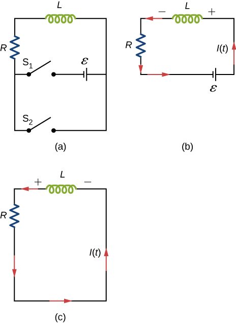
A circuit with resistance and self-inductance is known as an RL circuit. Figure 14.12(a) shows an RL circuit consisting of a resistor, an inductor, a constant source of emf, and switches and When is closed, the circuit is equivalent to a single-loop circuit consisting of a resistor and an inductor connected across a source of emf (Figure 14.12(b)). When is opened and is closed, the circuit becomes a single-loop circuit with only a resistor and an inductor (Figure 14.12(c)).
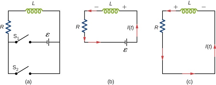
We first consider the RL circuit of Figure 14.12(b). Once is closed and is open, the source of emf produces a current in the circuit. If there were no self-inductance in the circuit, the current would rise immediately to a steady value of However, from Faraday’s law, the increasing current produces an emf across the inductor. In accordance with Lenz’s law, the induced emf counteracts the increase in the current and is directed as shown in the figure. As a result, I(t) starts at zero and increases asymptotically to its final value.
Applying Kirchhoff’s loop rule to this circuit, we obtain
which is a first-order differential equation for I(t). Notice its similarity to the equation for a capacitor and resistor in series (See RC Circuits). Similarly, the solution to Equation 14.23 can be found by making substitutions in the equations relating the capacitor to the inductor. This gives
where
is the inductive time constant of the circuit.
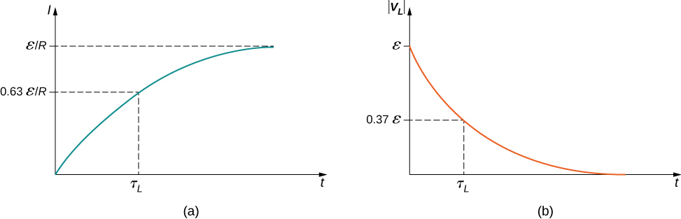
The current I(t) is plotted in Figure 14.13(a). It starts at zero, and as , I(t) approaches asymptotically. The induced emf is directly proportional to dI/dt, or the slope of the curve. Hence, while at its greatest immediately after the switches are thrown, the induced emf decreases to zero with time as the current approaches its final value of The circuit then becomes equivalent to a resistor connected across a source of emf.
The energy stored in the magnetic field of an inductor is
Thus, as the current approaches the maximum current , the stored energy in the inductor increases from zero and asymptotically approaches a maximum of
The time constant tells us how rapidly the current increases to its final value. At the current in the circuit is, from Equation 14.24,
which is of the final value . The smaller the inductive time constant the more rapidly the current approaches .
We can find the time dependence of the induced voltage across the inductor in this circuit by using and Equation 14.24:
The magnitude of this function is plotted in Figure 14.13(b). The greatest value of it occurs when dI/dt is greatest, which is immediately after is closed and is opened. In the approach to steady state, dI/dt decreases to zero. As a result, the voltage across the inductor also vanishes as
The time constant also tells us how quickly the induced voltage decays. At the magnitude of the induced voltage is
The voltage across the inductor therefore drops to about of its initial value after one time constant. The shorter the time constant the more rapidly the voltage decreases.
After enough time has elapsed so that the current has essentially reached its final value, the positions of the switches in Figure 14.12(a) are reversed, giving us the circuit in part (c). At the current in the circuit is With Kirchhoff’s loop rule, we obtain
The solution to this equation is similar to the solution of the equation for a discharging capacitor, with similar substitutions. The current at time t is then
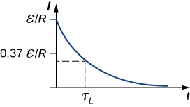
The current starts at and decreases with time as the energy stored in the inductor is depleted (Figure 14.14).
The time dependence of the voltage across the inductor can be determined from
This voltage is initially , and it decays to zero like the current. The energy stored in the magnetic field of the inductor, also decreases exponentially with time, as it is dissipated by Joule heating in the resistance of the circuit.
Summary
- When a series connection of a resistor and an inductor—an RL circuit—is connected to a voltage source, the time variation of the current is
(turning on),
where the initial current is - The characteristic time constant is where L is the inductance and R is the resistance.
- In the first time constant the current rises from zero to and to 0.632 of the remainder in every subsequent time interval
- When the inductor is shorted through a resistor, current decreases as
(turning off).
Current falls to in the first time interval , and to 0.368 of the remainder toward zero in each subsequent time
Conceptual Questions
Use Lenz’s law to explain why the initial current in the RL circuit of Figure 14.12(b) is zero.
As current flows through the inductor, there is a back current by Lenz’s law that is created to keep the net current at zero amps, the initial current.
When the current in the RL circuit of Figure 14.12(b) reaches its final value what is the voltage across the inductor? Across the resistor?
Does the time required for the current in an RL circuit to reach any fraction of its steady-state value depend on the emf of the battery?
no
An inductor is connected across the terminals of a battery. Does the current that eventually flows through the inductor depend on the internal resistance of the battery? Does the time required for the current to reach its final value depend on this resistance?
At what time is the voltage across the inductor of the RL circuit of Figure 14.12(b) a maximum?
At , or when the switch is first thrown.
In the simple RL circuit of Figure 14.12(b), can the emf induced across the inductor ever be greater than the emf of the battery used to produce the current?
If the emf of the battery of Figure 14.12(b) is reduced by a factor of 2, by how much does the steady-state energy stored in the magnetic field of the inductor change?
1/4
A steady current flows through a circuit with a large inductive time constant. When a switch in the circuit is opened, a large spark occurs across the terminals of the switch. Explain.
Describe how the currents through shown below vary with time after switch S is closed.
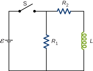
Initially, and , and after a long time has passed, and .
Discuss possible practical applications of RL circuits.
Problems
In Figure 14.12, , , and . Determine (a) the time constant of the circuit, (b) the initial current through the resistor, (c) the final current through the resistor, (d) the current through the resistor when and (e) the voltages across the inductor and the resistor when
For the circuit shown below, , and . After steady state is reached with closed and open, is closed and immediately thereafter is opened. Determine (a) the current through L at , (b) the current through L at , and (c) the voltages across L and at . .
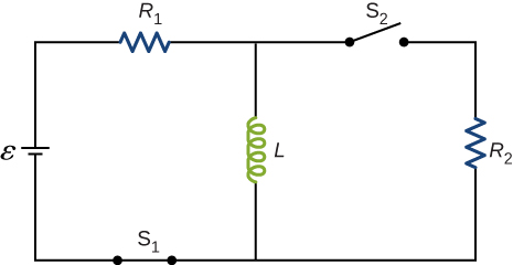
a. 4.0 A; b. 2.4 A; c. on R: ; on L:
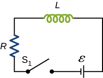
The current in the RL circuit shown here increases to of its steady-state value in 2.0 s. What is the time constant of the circuit?
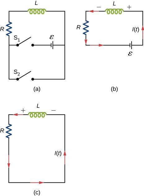
How long after switch is thrown does it take the current in the circuit shown to reach half its maximum value? Express your answer in terms of the time constant of the circuit.
Examine the circuit shown below in part (a). Determine dI/dt at the instant after the switch is thrown in the circuit of (a), thereby producing the circuit of (b). Show that if I were to continue to increase at this initial rate, it would reach its maximum in one time constant.
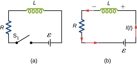
The current in the RL circuit shown below reaches half its maximum value in 1.75 ms after the switch is thrown. Determine (a) the time constant of the circuit and (b) the resistance of the circuit if .
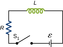
a. 2.52 ms; b.
Consider the circuit shown below. Find when (a) the switch S is first closed, (b) after the currents have reached steady-state values, and (c) at the instant the switch is reopened (after being closed for a long time).
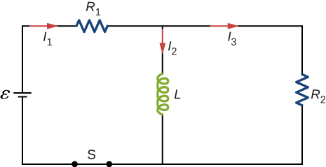
For the circuit shown below, , , , and . Find the values of (a) immediately after switch S is closed, (b) a long time after S is closed, (c) immediately after S is reopened, and (d) a long time after S is reopened.
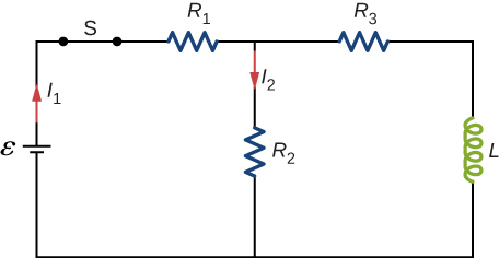
a. ; b. ; c. ; d.
For the circuit shown below, find the current through the inductor after the switch is reopened. The values of the components are the same as in the previous problem.
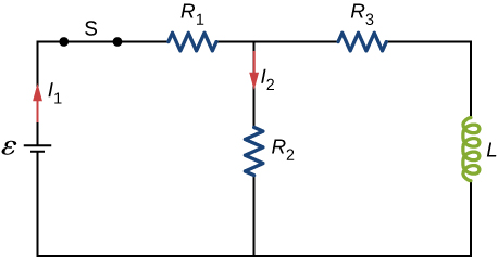
Show that for the circuit shown below, the initial energy stored in the inductor, , is equal to the total energy eventually dissipated in the resistor, .
proof
Adapted from University Physics Volume 2 by OpenStax (openstax.org), licensed under CC BY-NC-SA 4.0. Changes were made. License: CC-BY-NC-SA-4.0.