
14.1 Mutual Inductance
Inductance is the property of a device that tells us how effectively it induces an emf in another device. In other words, it is a physical quantity that expresses the effectiveness of a given device.
When two circuits carrying time-varying currents are close to one another, the magnetic flux through each circuit varies because of the changing current I in the other circuit. Consequently, an emf is induced in each circuit by the changing current in the other. This type of emf is therefore called a mutually induced emf, and the phenomenon that occurs is known as mutual inductance (M). As an example, let’s consider two tightly wound coils (Figure 14.2). Coils 1 and 2 have and turns and carry currents and respectively. The flux through a single turn of coil 2 produced by the magnetic field of the current in coil 1 is whereas the flux through a single turn of coil 1 due to the magnetic field of is
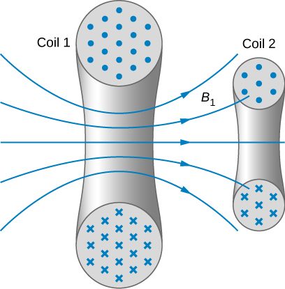
The mutual inductance of coil 2 with respect to coil 1 is the ratio of the flux through the turns of coil 2 produced by the magnetic field of the current in coil 1, divided by that current, that is,
Similarly, the mutual inductance of coil 1 with respect to coil 2 is
Like capacitance, mutual inductance is a geometric quantity. It depends on the shapes and relative positions of the two coils, and it is independent of the currents in the coils. The SI unit for mutual inductance M is called the henry (H) in honor of Joseph Henry (1799–1878), an American scientist who discovered induced emf independently of Faraday. Thus, we have . From Equation 14.1 and Equation 14.2, we can show that so we usually drop the subscripts associated with mutual inductance and write
The emf developed in either coil is found by combining Faraday’s law and the definition of mutual inductance. Since is the total flux through coil 2 due to , we obtain
where we have used the fact that M is a time-independent constant because the geometry is time-independent. Similarly, we have
In Equation 14.5, we can see the significance of the earlier description of mutual inductance (M) as a geometric quantity. The value of M neatly encapsulates the physical properties of circuit elements and allows us to separate the physical layout of the circuit from the dynamic quantities, such as the emf and the current. Equation 14.5 defines the mutual inductance in terms of properties in the circuit, whereas the previous definition of mutual inductance in Equation 14.1 is defined in terms of the magnetic flux experienced, regardless of circuit elements. You should be careful when using Equation 14.4 and Equation 14.5 because do not necessarily represent the total emfs in the respective coils. Each coil can also have an emf induced in it because of its self-inductance (self-inductance will be discussed in more detail in a later section).
A large mutual inductance M may or may not be desirable. We want a transformer to have a large mutual inductance. But an appliance, such as an electric clothes dryer, can induce a dangerous emf on its metal case if the mutual inductance between its coils and the case is large. One way to reduce mutual inductance is to counter-wind coils to cancel the magnetic field produced (Figure 14.3).
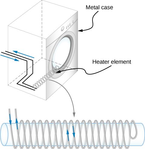
Digital signal processing is another example in which mutual inductance is reduced by counter-winding coils. The rapid on/off emf representing 1s and 0s in a digital circuit creates a complex time-dependent magnetic field. An emf can be generated in neighboring conductors. If that conductor is also carrying a digital signal, the induced emf may be large enough to switch 1s and 0s, with consequences ranging from inconvenient to disastrous.
Summary
- Inductance is the property of a device that expresses how effectively it induces an emf in another device.
- Mutual inductance is the effect of two devices inducing emfs in each other.
- A change in current in one circuit induces an emf in the second: where M is defined to be the mutual inductance between the two circuits and the minus sign is due to Lenz’s law.
- Symmetrically, a change in current through the second circuit induces an emf in the first: where M is the same mutual inductance as in the reverse process.
Conceptual Questions
Show that and which are both expressions for self-inductance, have the same units.
A 10-H inductor carries a current of 20 A. Describe how a 50-V emf can be induced across it.
The ignition circuit of an automobile is powered by a 12-V battery. How are we able to generate large voltages with this power source?
The induced current from the 12-V battery goes through an inductor, generating a large voltage.
When the current through a large inductor is interrupted with a switch, an arc appears across the open terminals of the switch. Explain.
Problems
When the current in one coil changes at a rate of 5.6 A/s, an emf of is induced in a second, nearby coil. What is the mutual inductance of the two coils?
An emf of is induced in a coil while the current in a nearby coil is decreasing at a rate of 2.7 A/s. What is the mutual inductance of the two coils?
Two coils close to each other have a mutual inductance of 32 mH. If the current in one coil decays according to , where and what is the emf induced in the second coil immediately after the current starts to decay? At
A coil of 40 turns is wrapped around a long solenoid of cross-sectional area The solenoid is 0.50 m long and has 500 turns. (a) What is the mutual inductance of this system? (b) The outer coil is replaced by a coil of 40 turns whose radius is three times that of the solenoid. What is the mutual inductance of this configuration?
a. ; b.
A 600-turn solenoid is 0.55 m long and 4.2 cm in diameter. Inside the solenoid, a small single-turn rectangular coil is fixed in place with its face perpendicular to the long axis of the solenoid. What is the mutual inductance of this system?
A toroidal coil has a mean radius of 16 cm and a cross-sectional area of ; it is wound uniformly with 1000 turns. A second toroidal coil of 750 turns is wound uniformly over the first coil. Ignoring the variation of the magnetic field within a toroid, determine the mutual inductance of the two coils.
A solenoid of turns has length and radius and a second smaller solenoid of turns has length and radius . The smaller solenoid is placed completely inside the larger solenoid so that their long axes coincide. What is the mutual inductance of the two solenoids?
Adapted from University Physics Volume 2 by OpenStax (openstax.org), licensed under CC BY-NC-SA 4.0. Changes were made. License: CC-BY-NC-SA-4.0.