
14.2 Self-Inductance and Inductors
Mutual inductance arises when a current in one circuit produces a changing magnetic field that induces an emf in another circuit. But can the magnetic field affect the current in the original circuit that produced the field? The answer is yes, and this is the phenomenon called self-inductance.
Inductors
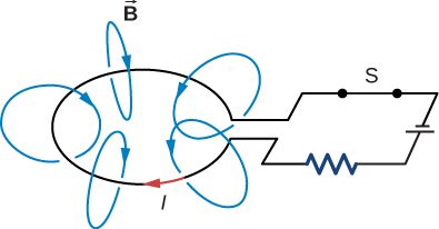
Figure 14.5 shows some of the magnetic field lines due to the current in a circular loop of wire. If the current is constant, the magnetic flux through the loop is also constant. However, if the current I were to vary with time—say, immediately after switch S is closed—then the magnetic flux would correspondingly change. Then Faraday’s law tells us that an emf would be induced in the circuit, where
Since the magnetic field due to a current-carrying wire is directly proportional to the current, the flux due to this field is also proportional to the current; that is,
This can also be written as
where the constant of proportionality L is known as the self-inductance of the wire loop. If the loop has N turns, this equation becomes
By convention, the positive sense of the normal to the loop is related to the current by the right-hand rule, so in Figure 14.5, the normal points downward. With this convention, is positive in Equation 14.9, so L always has a positive value.
For a loop with N turns, so the induced emf may be written in terms of the self-inductance as
When using this equation to determine L, it is easiest to ignore the signs of and calculate L as
Since self-inductance is associated with the magnetic field produced by a current, any configuration of conductors possesses self-inductance. For example, besides the wire loop, a long, straight wire has self-inductance, as does a coaxial cable. A coaxial cable is most commonly used by the cable television industry and may also be found connecting to your cable modem. Coaxial cables are used due to their ability to transmit electrical signals with minimal distortions. Coaxial cables have two long cylindrical conductors that possess current and a self-inductance that may have undesirable effects.
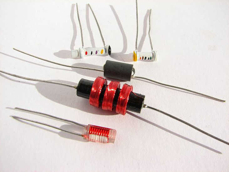
A circuit element used to provide self-inductance is known as an inductor. It is represented by the symbol shown in Figure 14.6, which resembles a coil of wire, the basic form of the inductor. Figure 14.7 shows several types of inductors commonly used in circuits.

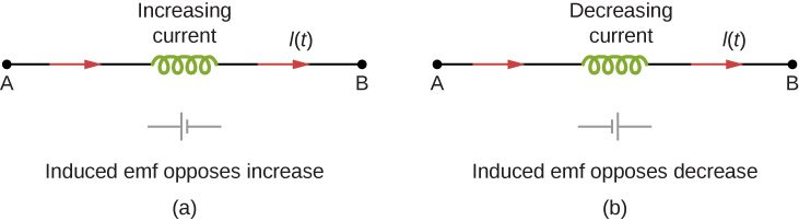
In accordance with Lenz’s law, the negative sign in Equation 14.10 indicates that the induced emf across an inductor always has a polarity that opposes the change in the current. For example, if the current flowing from A to B in Figure 14.8(a) were increasing, the induced emf (represented by the imaginary battery) would have the polarity shown in order to oppose the increase. If the current from A to B were decreasing, then the induced emf would have the opposite polarity, again to oppose the change in current (Figure 14.8(b)). Finally, if the current through the inductor were constant, no emf would be induced in the coil.
One common application of inductance is to allow traffic signals to sense when vehicles are waiting at a street intersection. An electrical circuit with an inductor is placed in the road underneath the location where a waiting car will stop. The body of the car increases the inductance and the circuit changes, sending a signal to the traffic lights to change colors. Similarly, metal detectors used for airport security employ the same technique. A coil or inductor in the metal detector frame acts as both a transmitter and a receiver. The pulsed signal from the transmitter coil induces a signal in the receiver. The self-inductance of the circuit is affected by any metal object in the path (Figure 14.9). Metal detectors can be adjusted for sensitivity and can also sense the presence of metal on a person.

Large induced voltages are found in camera flashes. Camera flashes use a battery, two inductors that function as a transformer, and a switching system or oscillator to induce large voltages. Recall from Oscillations on oscillations that “oscillation” is defined as the fluctuation of a quantity, or repeated regular fluctuations of a quantity, between two extreme values around an average value. Also recall (from Electromagnetic Induction on electromagnetic induction) that we need a changing magnetic field, brought about by a changing current, to induce a voltage in another coil. The oscillator system does this many times as the battery voltage is boosted to over 1000 volts. (You may hear the high-pitched whine from the transformer as the capacitor is being charged.) A capacitor stores the high voltage for later use in powering the flash.
A good approach for calculating the self-inductance of an inductor consists of the following steps:
To demonstrate this procedure, we now calculate the self-inductances of two inductors.
Cylindrical Solenoid
Consider a long, cylindrical solenoid with length l, cross-sectional area A, and N turns of wire. We assume that the length of the solenoid is so much larger than its diameter that we can take the magnetic field to be throughout the interior of the solenoid, that is, we ignore end effects in the solenoid. With a current I flowing through the coils, the magnetic field produced within the solenoid is
so the magnetic flux through one turn is
Using Equation 14.9, we find for the self-inductance of the solenoid,
If is the number of turns per unit length of the solenoid, we may write Equation 14.13 as
where is the volume of the solenoid. Notice that the self-inductance of a long solenoid depends only on its physical properties (such as the number of turns of wire per unit length and the volume), and not on the magnetic field or the current. This is true for inductors in general.
Rectangular Toroid
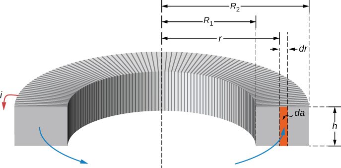
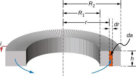
A toroid with a rectangular cross-section is shown in Figure 14.10. The inner and outer radii of the toroid are is the height of the toroid. Applying Ampère’s law in the same manner as we did in Example 2 in Section 13.4 for a toroid with a circular cross-section, we find the magnetic field inside a rectangular toroid is also given by
where r is the distance from the central axis of the toroid. Because the field changes within the toroid, we must calculate the flux by integrating over the toroid’s cross-section. Using the infinitesimal cross-sectional area element shown in Figure 14.10, we obtain
Now from Equation 14.16, we obtain for the self-inductance of a rectangular toroid
As expected, the self-inductance is a constant determined by only the physical properties of the toroid.
Summary
- Current changes in a device induce an emf in the device itself, called self-inductance, where L is the self-inductance of the inductor and is the rate of change of current through it. The minus sign indicates that emf opposes the change in current, as required by Lenz’s law. The unit of self-inductance and inductance is the henry (H), where .
- The self-inductance of a solenoid is where N is its number of turns in the solenoid, A is its cross-sectional area, l is its length, and is the permeability of free space.
- The self-inductance of a toroid is where N is its number of turns in the toroid, are the inner and outer radii of the toroid, h is the height of the toroid, and is the permeability of free space.
Conceptual Questions
Does self-inductance depend on the value of the magnetic flux? Does it depend on the current through the wire? Correlate your answers with the equation
Self-inductance is proportional to the magnetic flux and inversely proportional to the current. However, since the magnetic flux depends on the current I, these effects cancel out. This means that the self-inductance does not depend on the current. If the emf is induced across an element, it does depend on how the current changes with time.
Would the self-inductance of a 1.0 m long, tightly wound solenoid differ from the self-inductance per meter of an infinite, but otherwise identical, solenoid?
Discuss how you might determine the self-inductance per unit length of a long, straight wire.
Consider the ends of a wire a part of an RL circuit and determine the self-inductance from this circuit.
The self-inductance of a coil is zero if there is no current passing through the windings. True or false?
How does the self-inductance per unit length near the center of a solenoid (away from the ends) compare with its value near the end of the solenoid?
The magnetic field will flare out at the end of the solenoid so there is less flux through the last turn than through the middle of the solenoid.
Problems
An emf of 0.40 V is induced across a coil when the current through it changes uniformly from 0.10 to 0.60 A in 0.30 s. What is the self-inductance of the coil?
0.24 H
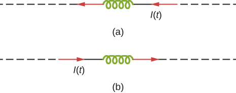
The current shown in part (a) below is increasing, whereas that shown in part (b) is decreasing. In each case, determine which end of the inductor is at the higher potential.
What is the rate at which the current though a 0.30-H coil is changing if an emf of 0.12 V is induced across the coil?
0.4 A/s
When a camera uses a flash, a fully charged capacitor discharges through an inductor. In what time must the 0.100-A current through a 2.00-mH inductor be switched on or off to induce a 500-V emf?
A coil with a self-inductance of 2.0 H carries a current that varies with time according to Find an expression for the emf induced in the coil.
A solenoid 50 cm long is wound with 500 turns of wire. The cross-sectional area of the coil is What is the self-inductance of the solenoid?
A coil with a self-inductance of 3.0 H carries a current that decreases at a uniform rate . What is the emf induced in the coil? Describe the polarity of the induced emf.
0.15 V. This is the same polarity as the emf driving the current.
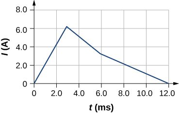
The current I(t) through a 5.0-mH inductor varies with time, as shown below. The resistance of the inductor is Calculate the voltage across the inductor at .
A long, cylindrical solenoid with 100 turns per centimeter has a radius of 1.5 cm. (a) Neglecting end effects, what is the self-inductance per unit length of the solenoid? (b) If the current through the solenoid changes at the rate 5.0 A/s, what is the emf induced per unit length?
a. 0.089 H/m; b. 0.44 V/m
Suppose that a rectangular toroid has 2000 windings and a self-inductance of 0.040 H. If , what is the ratio of its outer radius to its inner radius?
What is the self-inductance per meter of a coaxial cable whose inner radius is 0.50 mm and whose outer radius is 4.00 mm?
Adapted from University Physics Volume 2 by OpenStax (openstax.org), licensed under CC BY-NC-SA 4.0. Changes were made. License: CC-BY-NC-SA-4.0.