
20.1 Current
Learning Objectives
By the end of this section, you will be able to:
- Define electric current, ampere, and drift velocity
- Describe the direction of charge flow in conventional current.
- Use drift velocity to calculate current and vice versa.
Electric Current
Electric current is defined to be the rate at which charge flows. A large current, such as that used to start a truck engine, moves a large amount of charge in a small time, whereas a small current, such as that used to operate a hand-held calculator, moves a small amount of charge over a long period of time. In equation form, electric current is defined to be
where is the amount of charge passing through a given area in time . (As in previous chapters, initial time is often taken to be zero, in which case .) (See Figure 20.2.) The SI unit for current is the ampere (A), named for the French physicist André-Marie Ampère (1775–1836). Since , we see that an ampere is one coulomb per second:
Not only are fuses and circuit breakers rated in amperes (or amps), so are many electrical appliances.
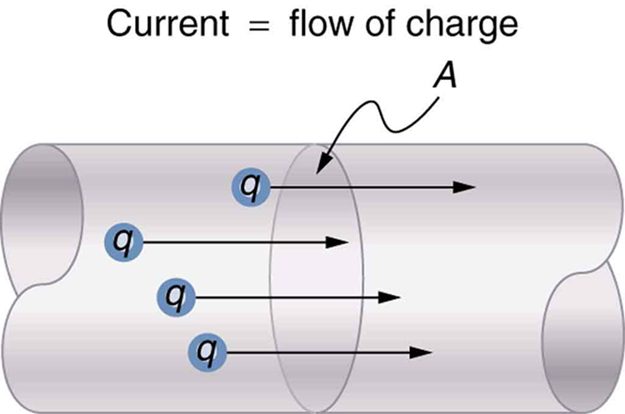
Figure 20.3 shows a simple circuit and the standard schematic representation of a battery, conducting path, and load (a resistor). Schematics are very useful in visualizing the main features of a circuit. A single schematic can represent a wide variety of situations. The schematic in Figure 20.3 (b), for example, can represent anything from a truck battery connected to a headlight lighting the street in front of the truck to a small battery connected to a penlight lighting a keyhole in a door. Such schematics are useful because the analysis is the same for a wide variety of situations. We need to understand a few schematics to apply the concepts and analysis to many more situations.
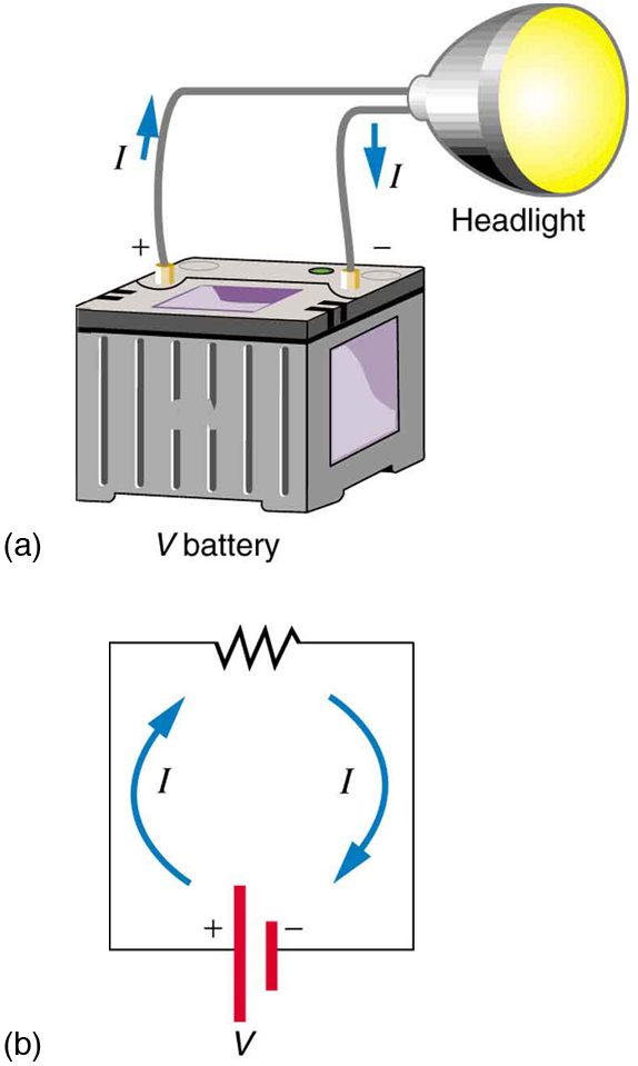
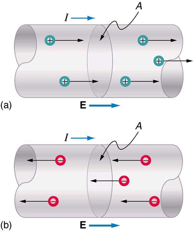
Note that the direction of current flow in Figure 20.3 is from positive to negative. The direction of conventional current is the direction that positive charge would flow. Depending on the situation, positive charges, negative charges, or both may move. In metal wires, for example, current is carried by electrons—that is, negative charges move. In ionic solutions, such as salt water, both positive and negative charges move. This is also true in nerve cells. A Van de Graaff generator used for nuclear research can produce a current of pure positive charges, such as protons. Figure 20.4 illustrates the movement of charged particles that compose a current. The fact that conventional current is taken to be in the direction that positive charge would flow can be traced back to American politician and scientist Benjamin Franklin in the 1700s. He named the type of charge associated with electrons negative, long before they were known to carry current in so many situations. Franklin, in fact, was totally unaware of the small-scale structure of electricity.
It is important to realize that there is an electric field in conductors responsible for producing the current, as illustrated in Figure 20.4. Unlike static electricity, where a conductor in equilibrium cannot have an electric field in it, conductors carrying a current have an electric field and are not in static equilibrium. An electric field is needed to supply energy to move the charges.
Drift Velocity
Electrical signals are known to move very rapidly. Telephone conversations carried by currents in wires cover large distances without noticeable delays. Lights come on as soon as a switch is flicked. Most electrical signals carried by currents travel at speeds on the order of , a significant fraction of the speed of light. Interestingly, the individual charges that make up the current move much more slowly on average, typically drifting at speeds on the order of . How do we reconcile these two speeds, and what does it tell us about standard conductors?
The high speed of electrical signals results from the fact that the force between charges acts rapidly at a distance. Thus, when a free charge is forced into a wire, as in Figure 20.5, the incoming charge pushes other charges ahead of it, which in turn push on charges farther down the line. The density of charge in a system cannot easily be increased, and so the signal is passed on rapidly. The resulting electrical shock wave moves through the system at nearly the speed of light. To be precise, this rapidly moving signal or shock wave is a rapidly propagating change in electric field.
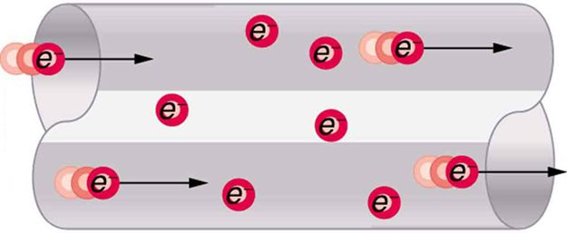
Good conductors have large numbers of free charges in them. In metals, the free charges are free electrons. Figure 20.6 shows how free electrons move through an ordinary conductor. The distance that an individual electron can move between collisions with atoms or other electrons is quite small. The electron paths thus appear nearly random, like the motion of atoms in a gas. But there is an electric field in the conductor that causes the electrons to drift in the direction shown (opposite to the field, since they are negative). The drift velocity is the average velocity of the free charges. Drift velocity is quite small, since there are so many free charges. If we have an estimate of the density of free electrons in a conductor, we can calculate the drift velocity for a given current. The larger the density, the lower the velocity required for a given current.
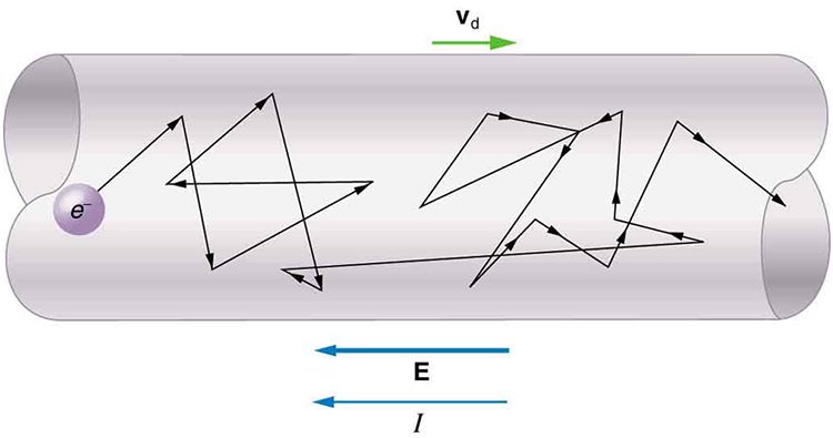
The free-electron collisions transfer energy to the atoms of the conductor. The electric field does work in moving the electrons through a distance, but that work does not increase the kinetic energy (nor speed, therefore) of the electrons. The work is transferred to the conductor’s atoms, possibly increasing temperature. Thus a continuous power input is required to keep a current flowing. An exception, of course, is found in superconductors, for reasons we shall explore in a later chapter. Superconductors can have a steady current without a continual supply of energy—a great energy savings. In contrast, the supply of energy can be useful, such as in a lightbulb filament. The supply of energy is necessary to increase the temperature of the tungsten filament, so that the filament glows.
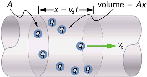
We can obtain an expression for the relationship between current and drift velocity by considering the number of free charges in a segment of wire, as illustrated in Figure 20.7. The number of free charges per unit volume is given the symbol and depends on the material. The shaded segment has a volume , so that the number of free charges in it is . The charge in this segment is thus , where is the amount of charge on each carrier. (Recall that for electrons, is .) Current is charge moved per unit time; thus, if all the original charges move out of this segment in time , the current is
Note that is the magnitude of the drift velocity, , since the charges move an average distance in a time . Rearranging terms gives
where is the current through a wire of cross-sectional area made of a material with a free charge density . The carriers of the current each have charge and move with a drift velocity of magnitude .
Note that simple drift velocity is not the entire story. The speed of an electron is much greater than its drift velocity. In addition, not all of the electrons in a conductor can move freely, and those that do might move somewhat faster or slower than the drift velocity. So what do we mean by free electrons? Atoms in a metallic conductor are packed in the form of a lattice structure. Some electrons are far enough away from the atomic nuclei that they do not experience the attraction of the nuclei as much as the inner electrons do. These are the free electrons. They are not bound to a single atom but can instead move freely among the atoms in a “sea” of electrons. These free electrons respond by accelerating when an electric field is applied. Of course as they move they collide with the atoms in the lattice and other electrons, generating thermal energy, and the conductor gets warmer. In an insulator, the organization of the atoms and the structure do not allow for such free electrons.
Test Prep for AP Courses
Which of the following can be explained on the basis of conservation of charge in a closed circuit consisting of a battery, resistor, and metal wires?
- The number of electrons leaving the battery will be equal to the number of electrons entering the battery.
- The number of electrons leaving the battery will be less than the number of electrons entering the battery.
- The number of protons leaving the battery will be equal to the number of protons entering the battery.
- The number of protons leaving the battery will be less than the number of protons entering the battery.
(a)
When a battery is connected to a bulb, there is 2.5 A of current in the circuit. What amount of charge will flow though the circuit in a time of 0.5 s?
- 0.5 C
- 1 C
- 1.25 C
- 1.5 C
If 0.625 × 10²⁰ electrons flow through a circuit each second, what is the current in the circuit?
10 A
Two students calculate the charge flowing through a circuit. The first student concludes that 300 C of charge flows in 1 minute. The second student concludes that 3.125 × 10¹⁹ electrons flow per second. If the current measured in the circuit is 5 A, which of the two students (if any) have performed the calculations correctly?
Section Summary
- Electric current is the rate at which charge flows, given by where is the amount of charge passing through an area in time .
- The direction of conventional current is taken as the direction in which positive charge moves.
- The SI unit for current is the ampere (A), where
- Current is the flow of free charges, such as electrons and ions.
- Drift velocity is the average speed at which these charges move.
- Current is proportional to drift velocity , as expressed in the relationship . Here, is the current through a wire of cross-sectional area . The wire’s material has a free-charge density , and each carrier has charge and a drift velocity .
- Electrical signals travel at speeds about times greater than the drift velocity of free electrons.
Conceptual Questions
Can a wire carry a current and still be neutral—that is, have a total charge of zero? Explain.
Car batteries are rated in ampere-hours (). To what physical quantity do ampere-hours correspond (voltage, charge,...), and what relationship do ampere-hours have to energy content?
If two different wires having identical cross-sectional areas carry the same current, will the drift velocity be higher or lower in the better conductor? Explain in terms of the equation , by considering how the density of charge carriers relates to whether or not a material is a good conductor.
Why are two conducting paths from a voltage source to an electrical device needed to operate the device?
In cars, one battery terminal is connected to the metal body. How does this allow a single wire to supply current to electrical devices rather than two wires?
Why isn’t a bird sitting on a high-voltage power line electrocuted? Contrast this with the situation in which a large bird hits two wires simultaneously with its wings.
Problems & Exercises
What is the current in milliamperes produced by the solar cells of a pocket calculator through which 4.00 C of charge passes in 4.00 h?
0.278 mA
A total of 600 C of charge passes through a flashlight in 0.500 h. What is the average current?
What is the current when a typical static charge of moves from your finger to a metal doorknob in ?
0.250 A
Find the current when 2.00 nC jumps between your comb and hair over a time interval.
A large lightning bolt had a 20,000-A current and moved 30.0 C of charge. What was its duration?
1.50ms
The 200-A current through a spark plug moves 0.300 mC of charge. How long does the spark last?
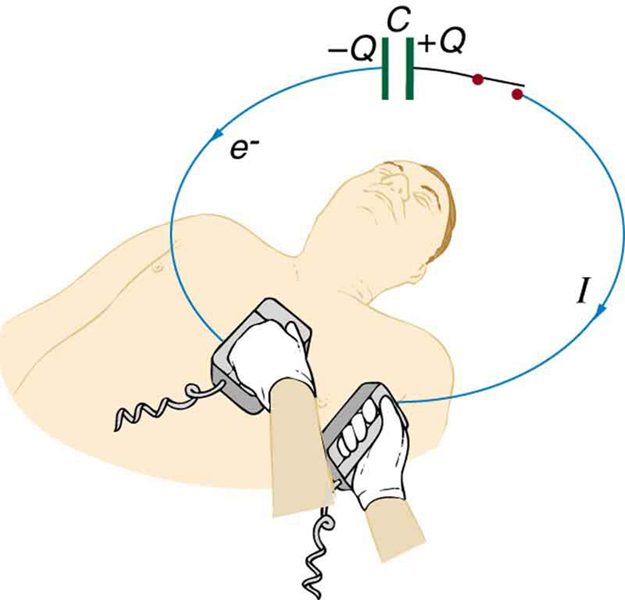
(a) A defibrillator sends a 6.00-A current through the chest of a patient by applying a 10,000-V potential as in the figure below. What is the resistance of the path? (b) The defibrillator paddles make contact with the patient through a conducting gel that greatly reduces the path resistance. Discuss the difficulties that would ensue if a larger voltage were used to produce the same current through the patient, but with the path having perhaps 50 times the resistance. (Hint: The current must be about the same, so a higher voltage would imply greater power. Use this equation for power: .)
(a)
(b) If a 50 times larger resistance existed, keeping the current about the same, the power would be increased by a factor of about 50 (based on the equation ), causing much more energy to be transferred to the skin, which could cause serious burns. The gel used reduces the resistance, and therefore reduces the power transferred to the skin.
During open-heart surgery, a defibrillator can be used to bring a patient out of cardiac arrest. The resistance of the path is and a 10.0-mA current is needed. What voltage should be applied?
(a) A defibrillator passes 12.0 A of current through the torso of a person for 0.0100 s. How much charge moves? (b) How many electrons pass through the wires connected to the patient? (See figure two problems earlier.)
(a) 0.120 C
(b)
A clock battery wears out after moving 10,000 C of charge through the clock at a rate of 0.500 mA. (a) How long did the clock run? (b) How many electrons per second flowed?
The batteries of a submerged non-nuclear submarine supply 1000 A at full speed ahead. How long does it take to move Avogadro’s number () of electrons at this rate?
96.3 s
Electron guns are used in X-ray tubes. The electrons are accelerated through a relatively large voltage and directed onto a metal target, producing X-rays. (a) How many electrons per second strike the target if the current is 0.500 mA? (b) What charge strikes the target in 0.750 s?
A large cyclotron directs a beam of nuclei onto a target with a beam current of 0.250 mA. (a) How many nuclei per second is this? (b) How long does it take for 1.00 C to strike the target? (c) How long before 1.00 mol of nuclei strike the target?
(a)
(b)
(c)
Repeat the above example on Example 3, but for a wire made of silver and given there is one free electron per silver atom.
Using the results of the above example on Example 3, find the drift velocity in a copper wire of twice the diameter and carrying 20.0 A.
A 14-gauge copper wire has a diameter of 1.628 mm. What magnitude current flows when the drift velocity is 1.00 mm/s? (See above example on Example 3 for useful information.)
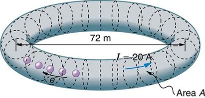
SPEAR, a storage ring about 72.0 m in diameter at the Stanford Linear Accelerator (closed in 2009), has a 20.0-A circulating beam of electrons that are moving at nearly the speed of light. (See Figure 20.9.) How many electrons are in the beam?
Adapted from College Physics 2e by OpenStax (openstax.org), licensed under CC BY-NC-SA 4.0. Changes were made. License: CC-BY-NC-SA-4.0.