
11.6 The Hall Effect
In 1879, E.H. Hall devised an experiment that can be used to identify the sign of the predominant charge carriers in a conducting material. From a historical perspective, this experiment was the first to demonstrate that the charge carriers in most metals are negative.
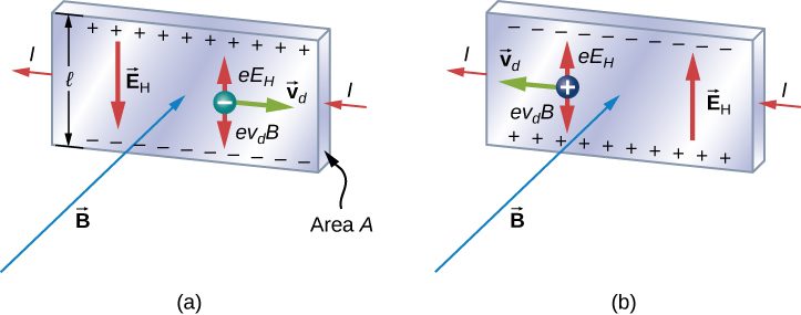
We investigate the Hall effect by studying the motion of the free electrons along a metallic strip of width l in a constant magnetic field (Figure 11.17). The electrons are moving from left to right, so the magnetic force they experience pushes them to the bottom edge of the strip. This leaves an excess of positive charge at the top edge of the strip, resulting in an electric field E directed from top to bottom. The charge concentration at both edges builds up until the electric force on the electrons in one direction is balanced by the magnetic force on them in the opposite direction. Equilibrium is reached when:
where e is the magnitude of the electron charge, is the drift speed of the electrons, and E is the magnitude of the electric field created by the separated charge. Solving this for the drift speed results in
A scenario where the electric and magnetic fields are perpendicular to one another is called a crossed-field situation. If these fields produce equal and opposite forces on a charged particle with the velocity that equates the forces, these particles are able to pass through an apparatus, called a velocity selector, undeflected. This velocity is represented in Equation 11.25. Any other velocity of a charged particle sent into the same fields would be deflected by the magnetic force or electric force.
Going back to the Hall effect, if the current in the strip is I, then from Current and Resistance, we know that
where n is the number of charge carriers per volume and A is the cross-sectional area of the strip. Combining the equations for and I results in
The field E is related to the potential difference V between the edges of the strip by
The quantity V is called the Hall potential and can be measured with a voltmeter. Finally, combining the equations for I and E gives us
where the upper edge of the strip in Figure 11.17 is positive with respect to the lower edge.
We can also combine Equation 11.24 and Equation 11.28 to get an expression for the Hall voltage in terms of the magnetic field:
What if the charge carriers are positive, as in Figure 11.17? For the same current I, the magnitude of V is still given by Equation 11.29. However, the upper edge is now negative with respect to the lower edge. Therefore, by simply measuring the sign of V, we can determine the sign of the majority charge carriers in a metal.
Hall potential measurements show that electrons are the dominant charge carriers in most metals. However, Hall potentials indicate that for a few metals, such as tungsten, beryllium, and many semiconductors, the majority of charge carriers are positive. It turns out that conduction by positive charge is caused by the migration of missing electron sites (called holes) on ions. Conduction by holes is studied later in Condensed Matter Physics.
The Hall effect can be used to measure magnetic fields. If a material with a known density of charge carriers n is placed in a magnetic field and V is measured, then the field can be determined from Equation 11.29. In research laboratories where the fields of electromagnets used for precise measurements have to be extremely steady, a “Hall probe” is commonly used as part of an electronic circuit that regulates the field.
Summary
- Perpendicular electric and magnetic fields exert equal and opposite forces for a specific velocity of entering particles, thereby acting as a velocity selector. The velocity that passes through undeflected is calculated by
- The Hall effect can be used to measure the sign of the majority of charge carriers for metals. It can also be used to measure a magnetic field.
Conceptual Questions
Hall potentials are much larger for poor conductors than for good conductors with the same current. Why?
Poor conductors have a lower charge carrier density, n, which, based on the Hall effect formula, relates to a higher Hall potential. Good conductors have a higher charge carrier density, thereby a lower Hall potential.
Problems
A strip of copper is placed in a uniform magnetic field of magnitude 2.5 T. The Hall electric field is measured to be (a) What is the drift speed of the conduction electrons? (b) Assuming that n = electrons per cubic meter and that the cross-sectional area of the strip is calculate the current in the strip. (c) What is the Hall coefficient 1/nq?
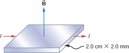
The cross-sectional dimensions of the copper strip shown are 2.0 cm by 2.0 mm. The strip carries a current of 100 A, and it is placed in a magnetic field of magnitude B = 1.5 T. What are the value and polarity of the Hall potential in the copper strip?
The magnitudes of the electric and magnetic fields in a velocity selector are and 0.080 T, respectively. (a) What speed must a proton have to pass through the selector? (b) Also calculate the speeds required for an alpha-particle and a singly ionized atom to pass through the selector.
A charged particle moves through a velocity selector at constant velocity. In the selector, E = and B = 0.250 T. When the electric field is turned off, the charged particle travels in a circular path of radius 3.33 mm. Determine the charge-to-mass ratio of the particle.
A Hall probe gives a reading of for a current of 2 A when it is placed in a magnetic field of 1 T. What is the magnetic field in a region where the reading is for 1.7 A of current?
Adapted from University Physics Volume 2 by OpenStax (openstax.org), licensed under CC BY-NC-SA 4.0. Changes were made. License: CC-BY-NC-SA-4.0.