
11.5 Force and Torque on a Current Loop
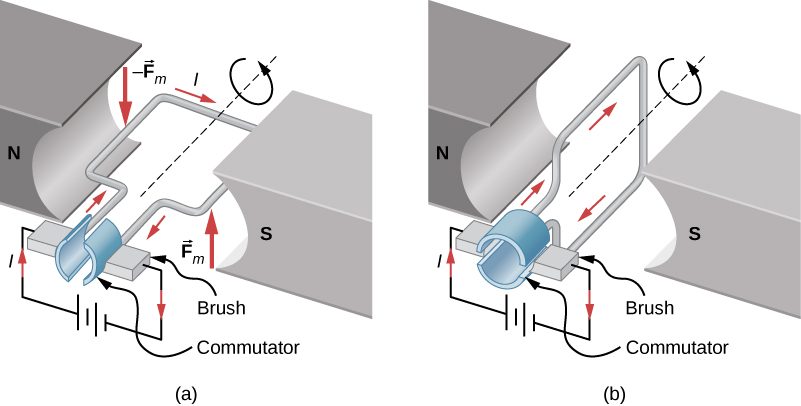
Motors are the most common application of magnetic force on current-carrying wires. Motors contain loops of wire in a magnetic field. When current is passed through the loops, the magnetic field exerts torque on the loops, which rotates a shaft. Electrical energy is converted into mechanical work in the process. Once the loop’s surface area is aligned with the magnetic field, the direction of current is reversed, so there is a continual torque on the loop (Figure 11.15). This reversal of the current is done with commutators and brushes. The commutator is set to reverse the current flow at set points to keep continual motion in the motor. A basic commutator has three contact areas to avoid and dead spots where the loop would have zero instantaneous torque at that point. The brushes press against the commutator, creating electrical contact between parts of the commutator during the spinning motion.
In a uniform magnetic field, a current-carrying loop of wire, such as a loop in a motor, experiences both forces and torques on the loop. Figure 11.16 shows a rectangular loop of wire that carries a current I and has sides of lengths a and b. The loop is in a uniform magnetic field: The magnetic force on a straight current-carrying wire of length l is given by To find the net force on the loop, we have to apply this equation to each of the four sides. The force on side 1 is
where the direction has been determined with the RHR-1. The current in side 3 flows in the opposite direction to that of side 1, so
The currents in sides 2 and 4 are perpendicular to and the forces on these sides are
We can now find the net force on the loop:
Although this result has been obtained for a rectangular loop, it is far more general and holds for current-carrying loops of arbitrary shapes; that is, there is no net force on a current loop in a uniform magnetic field.
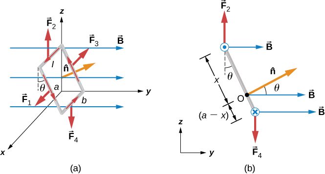
To find the net torque on the current loop shown in Figure 11.16, we first consider and Since they have the same line of action and are equal and opposite, the sum of their torques about any axis is zero (see Fixed-Axis Rotation). Thus, if there is any torque on the loop, it must be furnished by and Let’s calculate the torques around the axis that passes through point O of Figure 11.16 (a side view of the coil) and is perpendicular to the plane of the page. The point O is a distance x from side 2 and a distance from side 4 of the loop. The moment arms of and are and respectively, so the net torque on the loop is
This simplifies to
where is the area of the loop.
Notice that this torque is independent of x; it is therefore independent of where point O is located in the plane of the current loop. Consequently, the loop experiences the same torque from the magnetic field about any axis in the plane of the loop and parallel to the x-axis.
A closed-current loop is commonly referred to as a magnetic dipole and the term IA is known as its magnetic dipole moment Actually, the magnetic dipole moment is a vector that is defined as
where is a unit vector directed perpendicular to the plane of the loop (see Figure 11.16). The direction of is obtained with the RHR-2—if you curl the fingers of your right hand in the direction of current flow in the loop, then your thumb points along If the loop contains N turns of wire, then its magnetic dipole moment is given by
In terms of the magnetic dipole moment, the torque on a current loop due to a uniform magnetic field can be written simply as
This equation holds for a current loop in a two-dimensional plane of arbitrary shape.
Using a calculation analogous to that found in Capacitance for an electric dipole, the potential energy of a magnetic dipole is
Summary
- The net force on a current-carrying loop of any plane shape in a uniform magnetic field is zero.
- The net torque τ on a current-carrying loop of any shape in a uniform magnetic field is calculated using where is the magnetic dipole moment and is the magnetic field strength.
- The magnetic dipole moment is the product of the number of turns of wire N, the current in the loop I, and the area of the loop A or
Problems
(a) By how many percent is the torque of a motor decreased if its permanent magnets lose 5.0% of their strength? (b) How many percent would the current need to be increased to return the torque to original values?
a. so decreases by 5.00% if B decreases by 5.00%; b. 5.26% increase
(a) What is the maximum torque on a 150-turn square loop of wire 18.0 cm on a side that carries a 50.0-A current in a 1.60-T field? (b) What is the torque when θ is 10.9º?
Find the current through a loop needed to create a maximum torque of The loop has 50 square turns that are 15.0 cm on a side and is in a uniform 0.800-T magnetic field.
10.0 A
Calculate the magnetic field strength needed on a 200-turn square loop 20.0 cm on a side to create a maximum torque of 300 N ⋅ m if the loop is carrying 25.0 A.
Since the equation for torque on a current-carrying loop is τ = NIAB sin θ, the units of N ⋅ m must equal units of A ⋅ m2 T. Verify this.
(a) At what angle θ is the torque on a current loop 90.0% of maximum? (b) 50.0% of maximum? (c) 10.0% of maximum?
A proton has a magnetic field due to its spin. The field is similar to that created by a circular current loop in radius with a current of Find the maximum torque on a proton in a 2.50-T field. (This is a significant torque on a small particle.)
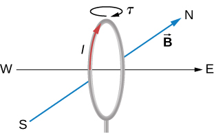
(a) A 200-turn circular loop of radius 50.0 cm is vertical, with its axis on an east-west line. A current of 100 A circulates clockwise in the loop when viewed from the east. Earth’s field here is due north, parallel to the ground, with a strength of What are the direction and magnitude of the torque on the loop? (b) Does this device have any practical applications as a motor?
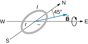
Repeat the previous problem, but with the loop lying flat on the ground with its current circulating counterclockwise (when viewed from above) in a location where Earth’s field is north, but at an angle 45.0° below the horizontal and with a strength of
Adapted from University Physics Volume 2 by OpenStax (openstax.org), licensed under CC BY-NC-SA 4.0. Changes were made. License: CC-BY-NC-SA-4.0.