
10.5 RC Circuits
When you use a flash camera, it takes a few seconds to charge the capacitor that powers the flash. The light flash discharges the capacitor in a tiny fraction of a second. Why does charging take longer than discharging? This question and several other phenomena that involve charging and discharging capacitors are discussed in this module.
Circuits with Resistance and Capacitance
An RC circuit is a circuit containing resistance and capacitance. As presented in Capacitance, the capacitor is an electrical component that stores electric charge, storing energy in an electric field.
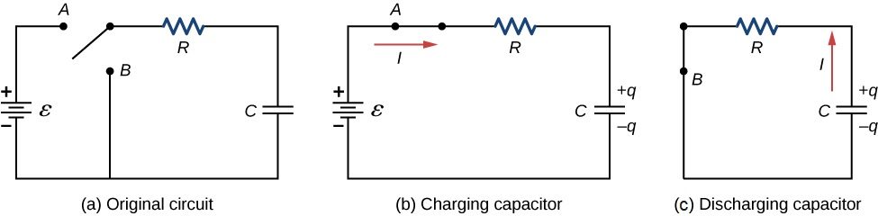
Figure 10.38(a) shows a simple RC circuit that employs a dc (direct current) voltage source , a resistor R, a capacitor C, and a two-position switch. The circuit allows the capacitor to be charged or discharged, depending on the position of the switch. When the switch is moved to position A, the capacitor charges, resulting in the circuit in part (b). When the switch is moved to position B, the capacitor discharges through the resistor.
Charging a Capacitor
We can use Kirchhoff’s loop rule to understand the charging of the capacitor. This results in the equation This equation can be used to model the charge as a function of time as the capacitor charges. Capacitance is defined as so the voltage across the capacitor is . Using Ohm’s law, the potential drop across the resistor is , and the current is defined as
This differential equation can be integrated to find an equation for the charge on the capacitor as a function of time.
Let , then The result is
Simplifying results in an equation for the charge on the charging capacitor as a function of time:
A graph of the charge on the capacitor versus time is shown in Figure 10.39(a). First note that as time approaches infinity, the exponential goes to zero, so the charge approaches the maximum charge and has units of coulombs. The units of RC are seconds, units of time. This quantity is known as the time constant:
At time , the charge is equal to of the maximum charge . Notice that the time rate change of the charge is the slope at a point of the charge versus time plot. The slope of the graph is large at time and approaches zero as time increases.
As the charge on the capacitor increases, the current through the resistor decreases, as shown in Figure 10.39(b). The current through the resistor can be found by taking the time derivative of the charge.
At time the current through the resistor is . As time approaches infinity, the current approaches zero. At time , the current through the resistor is
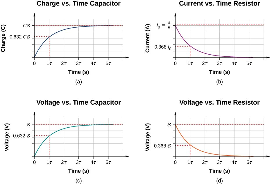
Figure 10.39(c) and Figure 10.39(d) show the voltage differences across the capacitor and the resistor, respectively. As the charge on the capacitor increases, the current decreases, as does the voltage difference across the resistor The voltage difference across the capacitor increases as
Discharging a Capacitor
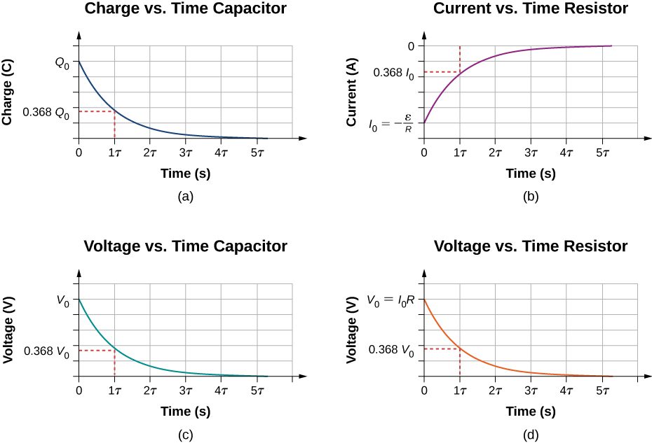
When the switch in Figure 10.38(a) is moved to position B, the circuit reduces to the circuit in part (c), and the charged capacitor is allowed to discharge through the resistor. A graph of the charge on the capacitor as a function of time is shown in Figure 10.40(a). Using Kirchhoff’s loop rule to analyze the circuit as the capacitor discharges results in the equation , which simplifies to . Using the definition of current and integrating the loop equation yields an equation for the charge on the capacitor as a function of time:
Here, Q is the initial charge on the capacitor and is the time constant of the circuit. As shown in the graph, the charge decreases exponentially from the initial charge, approaching zero as time approaches infinity.
The current as a function of time can be found by taking the time derivative of the charge:
The negative sign shows that the current flows in the opposite direction of the current found when the capacitor is charging, as shown in Figure 10.38. Figure 10.40 (parts (a) and (b)) shows an example of a plot of charge versus time and current versus time. A plot of the voltage difference across the capacitor and the voltage difference across the resistor as a function of time are shown in parts (c) and (d) of the figure. Note that the magnitudes of the charge, current, and voltage all decrease exponentially, approaching zero as time increases.
Now we can explain why the flash camera mentioned at the beginning of this section takes so much longer to charge than discharge: The resistance while charging is significantly greater than while discharging. The internal resistance of the battery accounts for most of the resistance while charging. As the battery ages, the increasing internal resistance makes the charging process even slower.
RC circuits have many applications. They can be used effectively as timers for applications such as intermittent windshield wipers, pace makers, and strobe lights. Some models of intermittent windshield wipers use a variable resistor to adjust the interval between sweeps of the wiper. Increasing the resistance increases the RC time constant, which increases the time between the operation of the wipers.
Another application is the pacemaker. The heart rate is normally controlled by electrical signals, which cause the muscles of the heart to contract and pump blood. When the heart rhythm is abnormal (the heartbeat is too high or too low), pace makers can be used to correct this abnormality. Pacemakers have sensors that detect body motion and breathing to increase the heart rate during physical activities, thus meeting the increased need for blood and oxygen, and an RC timing circuit can be used to control the time between voltage signals to the heart.
Looking ahead to the study of ac circuits (Alternating-Current Circuits), ac voltages vary as sine functions with specific frequencies. Periodic variations in voltage, or electric signals, are often recorded by scientists. These voltage signals could come from music recorded by a microphone or atmospheric data collected by radar. Occasionally, these signals can contain unwanted frequencies known as “noise.” RC filters can be used to filter out the unwanted frequencies.
In the study of electronics, a popular device known as a 555 timer provides timed voltage pulses. The time between pulses is controlled by an RC circuit. These are just a few of the countless applications of RC circuits.
The RC circuit has thousands of uses and is a very important circuit to study. Not only can it be used to time circuits, it can also be used to filter out unwanted frequencies in a circuit and used in power supplies, like the one for your computer, to help turn ac voltage to dc voltage.
Summary
- An RC circuit is one that has both a resistor and a capacitor.
- The time constant for an RC circuit is
- When an initially uncharged capacitor in series with a resistor is charged by a dc voltage source, the capacitor asymptotically approaches the maximum charge.
- As the charge on the capacitor increases, the current exponentially decreases from the initial current:
- If a capacitor with an initial charge Q is discharged through a resistor starting at , then its charge decreases exponentially. The current flows in the opposite direction, compared to when it charges, and the magnitude of the charge decreases with time.
Conceptual Questions
A battery, switch, capacitor, and lamp are connected in series. Describe what happens to the lamp when the switch is closed.
When making an ECG measurement, it is important to measure voltage variations over small time intervals. The time is limited by the RC constant of the circuit—it is not possible to measure time variations shorter than RC. How would you manipulate R and C in the circuit to allow the necessary measurements?
The time constant can be shortened by using a smaller resistor and/or a smaller capacitor. Care should be taken when reducing the resistance because the initial current will increase as the resistance decreases.
Problems
The timing device in an automobile’s intermittent wiper system is based on an RC time constant and utilizes a capacitor and a variable resistor. Over what range must R be made to vary to achieve time constants from 2.00 to 15.0 s?
A heart pacemaker fires 72 times a minute, each time a 25.0-nF capacitor is charged (by a battery in series with a resistor) to 0.632 of its full voltage. What is the value of the resistance?
The duration of a photographic flash is related to an RC time constant, which is for a certain camera. (a) If the resistance of the flash lamp is during discharge, what is the size of the capacitor supplying its energy? (b) What is the time constant for charging the capacitor, if the charging resistance is ?
a. ; b. 2.00 s
A 2.00- and a capacitor can be connected in series or parallel, as can a 25.0- and a resistor. Calculate the four RC time constants possible from connecting the resulting capacitance and resistance in series.
A resistor, an uncharged capacitor, and a 6.16-V emf are connected in series. (a) What is the initial current? (b) What is the RC time constant? (c) What is the current after one time constant? (d) What is the voltage on the capacitor after one time constant?
a. 12.3 mA; b. c. 4.53 mA; d. 3.89 V
A heart defibrillator being used on a patient has an RC time constant of 10.0 ms due to the resistance of the patient and the capacitance of the defibrillator. (a) If the defibrillator has a capacitance of what is the resistance of the path through the patient? (You may neglect the capacitance of the patient and the resistance of the defibrillator.) (b) If the initial voltage is 12.0 kV, how long does it take to decline to ?
An ECG monitor must have an RC time constant less than to be able to measure variations in voltage over small time intervals. (a) If the resistance of the circuit (due mostly to that of the patient’s chest) is , what is the maximum capacitance of the circuit? (b) Would it be difficult in practice to limit the capacitance to less than the value found in (a)?
a. b. No, in practice it would not be difficult to limit the capacitance to less than 100 nF, since typical capacitors range from fractions of a picofarad (pF) to milifarad (mF).
Using the exact exponential treatment, determine how much time is required to charge an initially uncharged 100-pF capacitor through a resistor to of its final voltage.
If you wish to take a picture of a bullet traveling at 500 m/s, then a very brief flash of light produced by an RC discharge through a flash tube can limit blurring. Assuming 1.00 mm of motion during one RC constant is acceptable, and given that the flash is driven by a capacitor, what is the resistance in the flash tube?
Adapted from University Physics Volume 2 by OpenStax (openstax.org), licensed under CC BY-NC-SA 4.0. Changes were made. License: CC-BY-NC-SA-4.0.