In Current and Resistance, we described the term ‘resistance’ and explained the basic design of a resistor. Basically, a resistor limits the flow of charge in a circuit and is an ohmic device where Most circuits have more than one resistor. If several resistors are connected together and connected to a battery, the current supplied by the battery depends on the equivalent resistance of the circuit.
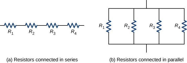
The equivalent resistance of a combination of resistors depends on both their individual values and how they are connected. The simplest combinations of resistors are series and parallel connections (Figure 10.11). In a series circuit, the output current of the first resistor flows into the input of the second resistor; therefore, the current is the same in each resistor. In a parallel circuit, all of the resistor leads on one side of the resistors are connected together and all the leads on the other side are connected together. In the case of a parallel configuration, each resistor has the same potential drop across it, and the currents through each resistor may be different, depending on the resistor. The sum of the individual currents equals the current that flows into the parallel connections.
Figure 10.11(a) For a series connection of resistors, the current is the same in each resistor. (b) For a parallel connection of resistors, the voltage is the same across each resistor.
Resistors in Series
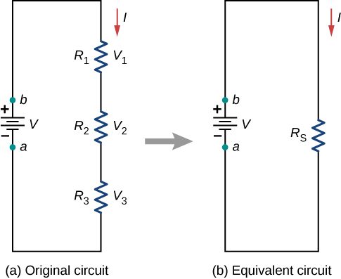
Resistors are said to be in series whenever the current flows through the resistors sequentially. Consider Figure 10.12, which shows three resistors in series with an applied voltage equal to Since there is only one path for the charges to flow through, the current is the same through each resistor. The equivalent resistance of a set of resistors in a series connection is equal to the algebraic sum of the individual resistances.
Figure 10.12(a) Three resistors connected in series to a voltage source. (b) The original circuit is reduced to an equivalent resistance and a voltage source.
In Figure 10.12, the current coming from the voltage source flows through each resistor, so the current through each resistor is the same. The current through the circuit depends on the voltage supplied by the voltage source and the resistance of the resistors. For each resistor, a potential drop occurs that is equal to the loss of electric potential energy as a current travels through each resistor. According to Ohm’s law, the potential drop V across a resistor when a current flows through it is calculated using the equation where I is the current in amps (A) and R is the resistance in ohms Since energy is conserved, and the voltage is equal to the potential energy per charge, the sum of the voltage applied to the circuit by the source and the potential drops across the individual resistors around a loop should be equal to zero:
This equation is often referred to as Kirchhoff’s loop law, which we will look at in more detail later in this chapter. For Figure 10.12, the sum of the potential drop of each resistor and the voltage supplied by the voltage source should equal zero:
Since the current through each component is the same, the equality can be simplified to an equivalent resistance, which is just the sum of the resistances of the individual resistors.
Any number of resistors can be connected in series. If N resistors are connected in series, the equivalent resistance is
One result of components connected in a series circuit is that if something happens to one component, it affects all the other components. For example, if several lamps are connected in series and one bulb burns out, all the other lamps go dark.
Let’s briefly summarize the major features of resistors in series:
Series resistances add together to get the equivalent resistance:
The same current flows through each resistor in series.
Individual resistors in series do not get the total source voltage, but divide it. The total potential drop across a series configuration of resistors is equal to the sum of the potential drops across each resistor.
Resistors in Parallel
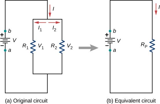
Figure 10.14 shows resistors in parallel, wired to a voltage source. Resistors are in parallel when one end of all the resistors are connected by a continuous wire of negligible resistance and the other end of all the resistors are also connected to one another through a continuous wire of negligible resistance. The potential drop across each resistor is the same. Current through each resistor can be found using Ohm’s law where the voltage is constant across each resistor. For example, an automobile’s headlights, radio, and other systems are wired in parallel, so that each subsystem utilizes the full voltage of the source and can operate completely independently. The same is true of the wiring in your house or any building.
Figure 10.14(a) Two resistors connected in parallel to a voltage source. (b) The original circuit is reduced to an equivalent resistance and a voltage source.
The current flowing from the voltage source in Figure 10.14 depends on the voltage supplied by the voltage source and the equivalent resistance of the circuit. In this case, the current flows from the voltage source and enters a junction, or node, where the circuit splits flowing through resistors and . As the charges flow from the battery, some go through resistor and some flow through resistor The sum of the currents flowing into a junction must be equal to the sum of the currents flowing out of the junction:
This equation is referred to as Kirchhoff’s junction rule and will be discussed in detail in the next section. In Figure 10.14, the junction rule gives . There are two loops in this circuit, which leads to the equations and . Note the voltage across the resistors in parallel are the same and the current is additive:
Generalizing to any number of N resistors, the equivalent resistance of a parallel connection is related to the individual resistances by
(10.3)
This relationship results in an equivalent resistance that is less than the smallest of the individual resistances. When resistors are connected in parallel, more current flows from the source than would flow for any of them individually, so the total resistance is lower.
Let us summarize the major features of resistors in parallel:
Equivalent resistance is found from
and is smaller than any individual resistance in the combination.
The potential drop across each resistor in parallel is the same.
Parallel resistors do not each get the total current; they divide it. The current entering a parallel combination of resistors is equal to the sum of the current through each resistor in parallel.
In this chapter, we introduced the equivalent resistance of resistors connect in series and resistors connected in parallel. You may recall that in Capacitance, we introduced the equivalent capacitance of capacitors connected in series and parallel. Circuits often contain both capacitors and resistors. Table 10.1 summarizes the equations used for the equivalent resistance and equivalent capacitance for series and parallel connections.
Table 10.1 Summary for Equivalent Resistance and Capacitance in Series and Parallel Combinations
Series combination
Parallel combination
Equivalent capacitance
Equivalent resistance
Combinations of Series and Parallel
More complex connections of resistors are often just combinations of series and parallel connections. Such combinations are common, especially when wire resistance is considered. In that case, wire resistance is in series with other resistances that are in parallel.
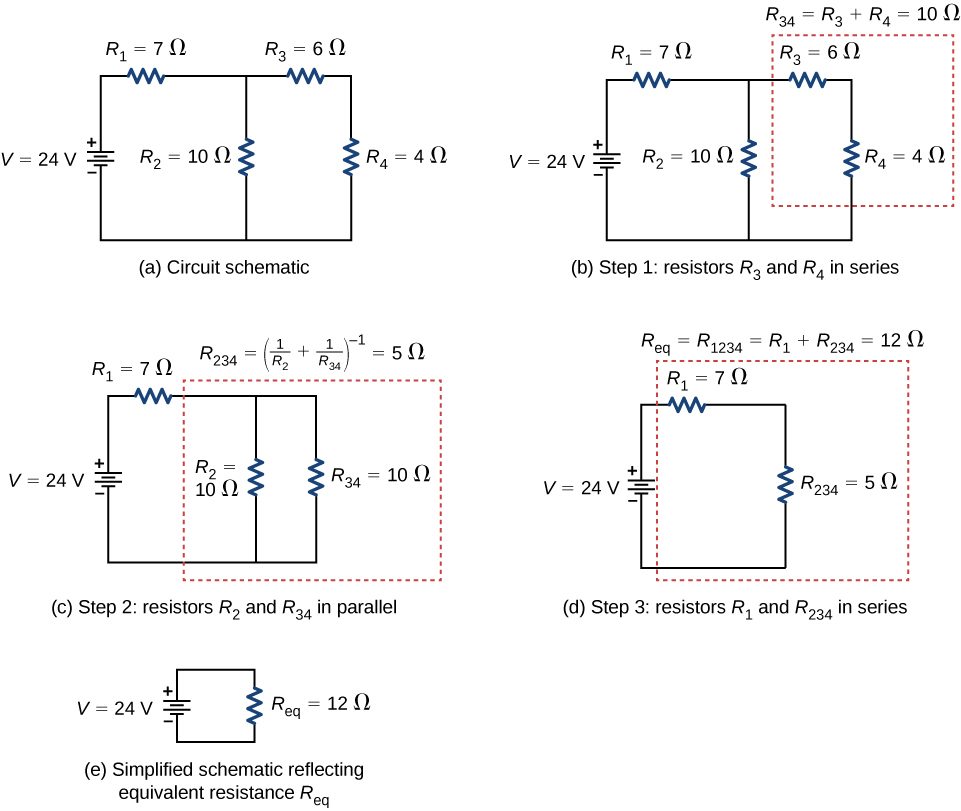
Combinations of series and parallel can be reduced to a single equivalent resistance using the technique illustrated in Figure 10.15. Various parts can be identified as either series or parallel connections, reduced to their equivalent resistances, and then further reduced until a single equivalent resistance is left. The process is more time consuming than difficult. Here, we note the equivalent resistance as
Figure 10.15(a) The original circuit of four resistors. (b) Step 1: The resistors and are in series and the equivalent resistance is (c) Step 2: The reduced circuit shows resistors and are in parallel, with an equivalent resistance of (d) Step 3: The reduced circuit shows that and are in series with an equivalent resistance of which is the equivalent resistance (e) The reduced circuit with a voltage source of with an equivalent resistance of This results in a current of from the voltage source.
Notice that resistors and are in series. They can be combined into a single equivalent resistance. One method of keeping track of the process is to include the resistors as subscripts. Here the equivalent resistance of and is
The circuit now reduces to three resistors, shown in Figure 10.15(c). Redrawing, we now see that resistors and constitute a parallel circuit. Those two resistors can be reduced to an equivalent resistance:
This step of the process reduces the circuit to two resistors, shown in in Figure 10.15(d). Here, the circuit reduces to two resistors, which in this case are in series. These two resistors can be reduced to an equivalent resistance, which is the equivalent resistance of the circuit:
The main goal of this circuit analysis is reached, and the circuit is now reduced to a single resistor and single voltage source.
Now we can analyze the circuit. The current provided by the voltage source is This current runs through resistor and is designated as The potential drop across can be found using Ohm’s law:
Looking at Figure 10.15(c), this leaves to be dropped across the parallel combination of and The current through can be found using Ohm’s law:
The resistors and are in series so the currents and are equal to
Using Ohm’s law, we can find the potential drop across the last two resistors. The potential drops are and The final analysis is to look at the power supplied by the voltage source and the power dissipated by the resistors. The power dissipated by the resistors is
The total energy is constant in any process. Therefore, the power supplied by the voltage source is Analyzing the power supplied to the circuit and the power dissipated by the resistors is a good check for the validity of the analysis; they should be equal.
Practical Implications
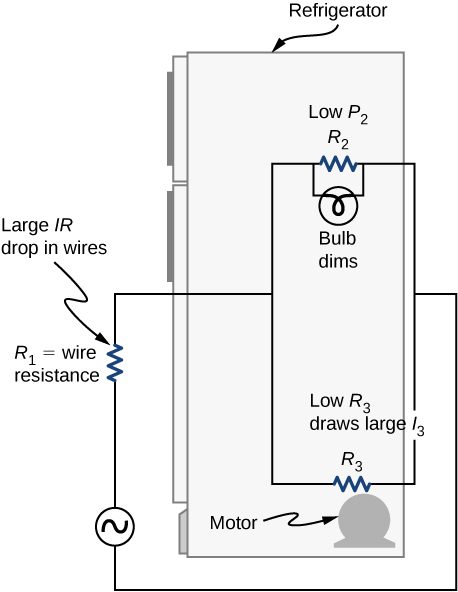
One implication of this last example is that resistance in wires reduces the current and power delivered to a resistor. If wire resistance is relatively large, as in a worn (or a very long) extension cord, then this loss can be significant. If a large current is drawn, the IR drop in the wires can also be significant and may become apparent from the heat generated in the cord.
For example, when you are rummaging in the refrigerator and the motor comes on, the refrigerator light dims momentarily. Similarly, you can see the passenger compartment light dim when you start the engine of your car (although this may be due to resistance inside the battery itself).
What is happening in these high-current situations is illustrated in Figure 10.17. The device represented by has a very low resistance, so when it is switched on, a large current flows. This increased current causes a larger IR drop in the wires represented by , reducing the voltage across the light bulb (which is ), which then dims noticeably.
Figure 10.17Why do lights dim when a large appliance is switched on? The answer is that the large current the appliance motor draws causes a significant IR drop in the wires and reduces the voltage across the light.
Summary
The equivalent resistance of an electrical circuit with resistors wired in a series is the sum of the individual resistances: .
Each resistor in a series circuit has the same amount of current flowing through it.
The potential drop, or power dissipation, across each individual resistor in a series is different, and their combined total is the power source input.
The equivalent resistance of an electrical circuit with resistors wired in parallel is less than the lowest resistance of any of the components and can be determined using the formula
Each resistor in a parallel circuit has the same full voltage of the source applied to it.
The current flowing through each resistor in a parallel circuit is different, depending on the resistance.
If a more complex connection of resistors is a combination of series and parallel, it can be reduced to a single equivalent resistance by identifying its various parts as series or parallel, reducing each to its equivalent, and continuing until a single resistance is eventually reached.
Conceptual Questions
A voltage occurs across an open switch. What is the power dissipated by the open switch?
The severity of a shock depends on the magnitude of the current through your body. Would you prefer to be in series or in parallel with a resistance, such as the heating element of a toaster, if you were shocked by it? Explain.
It would probably be better to be in series because the current will be less than if it were in parallel.
Suppose you are doing a physics lab that asks you to put a resistor into a circuit, but all the resistors supplied have a larger resistance than the requested value. How would you connect the available resistances to attempt to get the smaller value asked for?
Some light bulbs have three power settings (not including zero), obtained from multiple filaments that are individually switched and wired in parallel. What is the minimum number of filaments needed for three power settings?
two filaments, a low resistance and a high resistance, connected in parallel
Problems
(a) What is the resistance of a , a , and a resistor connected in series? (b) In parallel?
What are the largest and smallest resistances you can obtain by connecting a , a , and a resistor together?
largest, , smallest,
An 1800-W toaster, a 1400-W speaker, and a 75-W lamp are plugged into the same outlet in a 15-A fuse and 120-V circuit. (The three devices are in parallel when plugged into the same socket.) (a) What current is drawn by each device? (b) Will this combination blow the 15-A fuse?
Your car’s 30.0-W headlight and 2.40-kW starter are ordinarily connected in parallel in a 12.0-V system. What power would one headlight and the starter consume if connected in series to a 12.0-V battery? (Neglect any other resistance in the circuit and any change in resistance in the two devices.)
29.6 W
(a) Given a 48.0-V battery and and resistors, find the current and power for each when connected in series. (b) Repeat when the resistances are in parallel.
Referring to the example combining series and parallel circuits and Figure 10.16, calculate in the following two different ways: (a) from the known values of and ; (b) using Ohm’s law for . In both parts, explicitly show how you follow the steps in the Problem-Solving Strategy: Series and Parallel Resistors.
a. 0.74 A; b. 0.742 A
Referring to Figure 10.16, (a) Calculate and note how it compares with found in the first two example problems in this module. (b) Find the total power supplied by the source and compare it with the sum of the powers dissipated by the resistors.
Refer to Figure 10.17 and the discussion of lights dimming when a heavy appliance comes on. (a) Given the voltage source is 120 V, the wire resistance is and the bulb is nominally 75.0 W, what power will the bulb dissipate if a total of 15.0 A passes through the wires when the motor comes on? Assume negligible change in bulb resistance. (b) What power is consumed by the motor?
a. 60.8 W; b. 1.56 kW
Show that if two resistors and are combined and one is much greater than the other , (a) their series resistance is very nearly equal to the greater resistance and (b) their parallel resistance is very nearly equal to the smaller resistance .
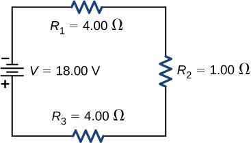
Consider the circuit shown below. The terminal voltage of the battery is (a) Find the equivalent resistance of the circuit. (b) Find the current through each resistor. (c) Find the potential drop across each resistor. (d) Find the power dissipated by each resistor. (e) Find the power supplied by the battery.
a. ; b.;
c. ; d. ; e.
Adapted from University Physics Volume 2 by OpenStax (openstax.org), licensed under CC BY-NC-SA 4.0. Changes were made. License: CC-BY-NC-SA-4.0.
These eBooks are a prerelease and are not yet certified conformant with WCAG 2.1 AA or ADA Title II. Every page is built against an automated accessibility gate, and the published editions will meet ADA Title II requirements when they release in late September 2026. If something is unusable, please tell us.