
10.1 Electromotive Force
Battery life is an essential consideration for every user of mobile phones, laptop computers, and electric vehicles. The reliability of a battery and its ability to hold a charge can impact every aspect of our day. For many people, battery reliability is even more important.
Each year, over 300,000 implantable cardioverter defibrillators (ICDs) are surgically provided to people at risk of sudden and life-threatening arrythmia, such as a heart beating too fast or irregularly. Similar to (and sometimes combined with) pacemakers, ICDs monitor patients' hearts and deliver electrical shocks to correct iregular activity. Since they must function properly at all times, battery life and reliability are critically important. Early ICDs had minimal power output and brief battery lives, which required frequent surgical replacement and made them impractical.
Esther Sans Takeuchi began addressing this problem in the 1980s, when she experimented with new chemical compositions and designs to increase the power and reliability of ICD and similar batteries. Her initial lithium-silver vanadium oxide batteries increased longevity and power output, making ICDs a viable option for hundreds of thousands of people. Takeuchi eventually became the chief scientist at the Department of Energy's Brookhaven National Laboratory, and her continued work has impacted a wide array of medical technologies, electric vehicles, and other battery applications.
In this section, we examine the principles of battery power and similar voltage sources, particularly the energy creation and internal resistance.
Introduction to Electromotive Force
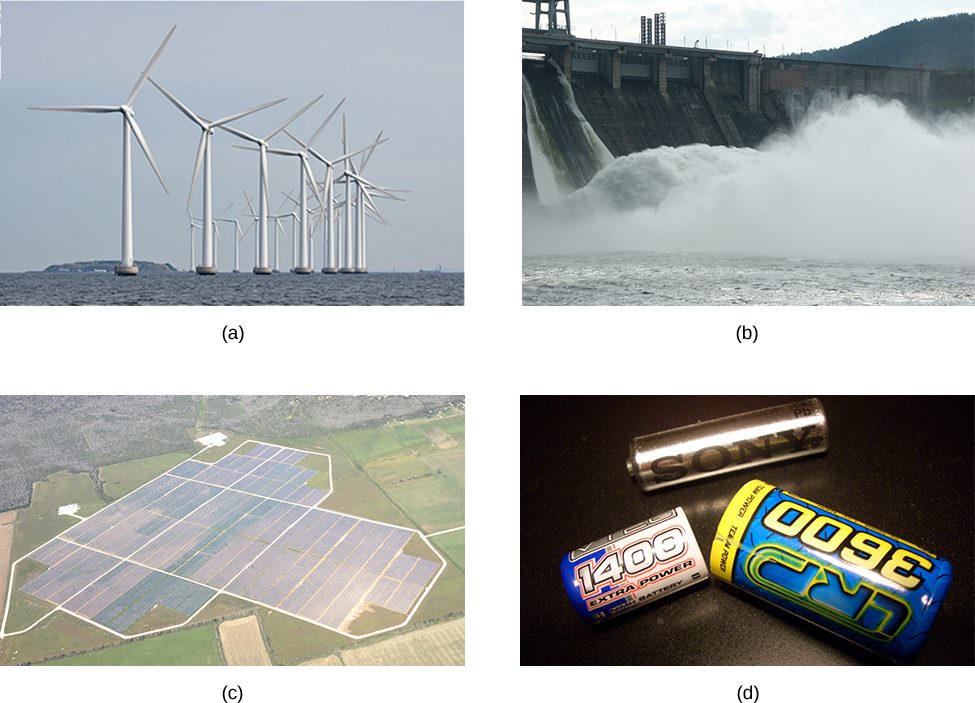
Voltage has many sources, a few of which are shown in Figure 10.2. All such devices create a potential difference and can supply current if connected to a circuit. A special type of potential difference is known as electromotive force (emf). The emf is not a force at all, but the term ‘electromotive force’ is used for historical reasons. It was coined by Alessandro Volta in the 1800s, when he invented the first battery, also known as the voltaic pile. Because the electromotive force is not a force, it is common to refer to these sources simply as sources of emf (pronounced as the letters “ee-em-eff”), instead of sources of electromotive force.
If the electromotive force is not a force at all, then what is the emf and what is a source of emf? To answer these questions, consider a simple circuit of a 12-V lamp attached to a 12-V battery, as shown in Figure 10.3. The battery can be modeled as a two-terminal device that keeps one terminal at a higher electric potential than the second terminal. The higher electric potential is sometimes called the positive terminal and is labeled with a plus sign. The lower-potential terminal is sometimes called the negative terminal and labeled with a minus sign. This is the source of the emf.
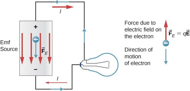
When the emf source is not connected to the lamp, there is no net flow of charge within the emf source. Once the battery is connected to the lamp, charges flow from one terminal of the battery, through the lamp (causing the lamp to light), and back to the other terminal of the battery. If we consider positive (conventional) current flow, positive charges leave the positive terminal, travel through the lamp, and enter the negative terminal.
Positive current flow is useful for most of the circuit analysis in this chapter, but in metallic wires and resistors, electrons contribute the most to current, flowing in the opposite direction of positive current flow. Therefore, it is more realistic to consider the movement of electrons for the analysis of the circuit in Figure 10.3. The electrons leave the negative terminal, travel through the lamp, and return to the positive terminal. In order for the emf source to maintain the potential difference between the two terminals, negative charges (electrons) must be moved from the positive terminal to the negative terminal. The emf source acts as a charge pump, moving negative charges from the positive terminal to the negative terminal to maintain the potential difference. This increases the potential energy of the charges and, therefore, the electric potential of the charges.
The force on the negative charge from the electric field is in the opposite direction of the electric field, as shown in Figure 10.3. In order for the negative charges to be moved to the negative terminal, work must be done on the negative charges. This requires energy, which comes from chemical reactions in the battery. The potential is kept high on the positive terminal and low on the negative terminal to maintain the potential difference between the two terminals. The emf is equal to the work done on the charge per unit charge when there is no current flowing. Since the unit for work is the joule and the unit for charge is the coulomb, the unit for emf is the volt
The terminal voltage of a battery is voltage measured across the terminals of the battery. An ideal battery is an emf source that maintains a constant terminal voltage, independent of the current between the two terminals. An ideal battery has no internal resistance, and the terminal voltage is equal to the emf of the battery. In the next section, we will show that a real battery does have internal resistance and the terminal voltage is always less than the emf of the battery.
The Origin of Battery Potential
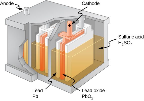
The combination of chemicals and the makeup of the terminals in a battery determine its emf. The lead acid battery used in cars and other vehicles is one of the most common combinations of chemicals. Figure 10.4 shows a single cell (one of six) of this battery. The cathode (positive) terminal of the cell is connected to a lead oxide plate, whereas the anode (negative) terminal is connected to a lead plate. Both plates are immersed in sulfuric acid, the electrolyte for the system.
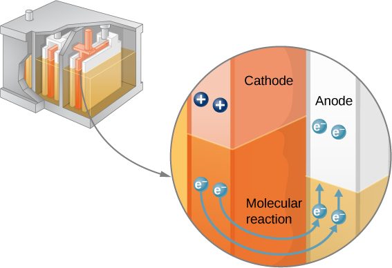
Knowing a little about how the chemicals in a lead-acid battery interact helps in understanding the potential created by the battery. Figure 10.5 shows the result of a single chemical reaction. Two electrons are placed on the anode, making it negative, provided that the cathode supplies two electrons. This leaves the cathode positively charged, because it has lost two electrons. In short, a separation of charge has been driven by a chemical reaction.
Note that the reaction does not take place unless there is a complete circuit to allow two electrons to be supplied to the cathode. Under many circumstances, these electrons come from the anode, flow through a resistance, and return to the cathode. Note also that since the chemical reactions involve substances with resistance, it is not possible to create the emf without an internal resistance.
You are likely familiar with many other types of batteries, such as the lithium-ion batteries found in many devices. These function in the same general way as lead-acid batteries, but utilize different chemicals. The specific compounds vary significantly, and researchers and companies continually innovate based on the requirements of each device. In many cases, the anode is composed of graphite, silicon-based materials, or metallic lithium. The cathode is often composed of lithium oxide compound, which may also contain manganese, cobalt, or other materials. And the electrolyte is usually a type of lithium salt.
Internal Resistance and Terminal Voltage
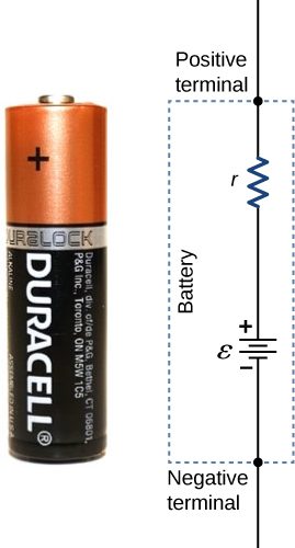
The amount of resistance to the flow of current within the voltage source is called the internal resistance. The internal resistance r of a battery can behave in complex ways. It generally increases as a battery is depleted, due to the oxidation of the plates or the reduction of the acidity of the electrolyte. However, internal resistance may also depend on the magnitude and direction of the current through a voltage source, its temperature, and even its history. The internal resistance of rechargeable nickel-cadmium cells, for example, depends on how many times and how deeply they have been depleted. A simple model for a battery consists of an idealized emf source and an internal resistance r (Figure 10.6).
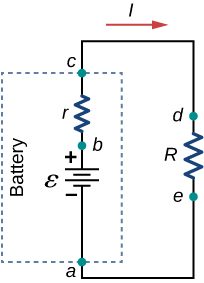
Suppose an external resistor, known as the load resistance R, is connected to a voltage source such as a battery, as in Figure 10.7. The figure shows a model of a battery with an emf , an internal resistance r, and a load resistor R connected across its terminals. Using conventional current flow, positive charges leave the positive terminal of the battery, travel through the resistor, and return to the negative terminal of the battery. The terminal voltage of the battery depends on the emf, the internal resistance, and the current, and is equal to
For a given emf and internal resistance, the terminal voltage decreases as the current increases due to the potential drop Ir of the internal resistance.
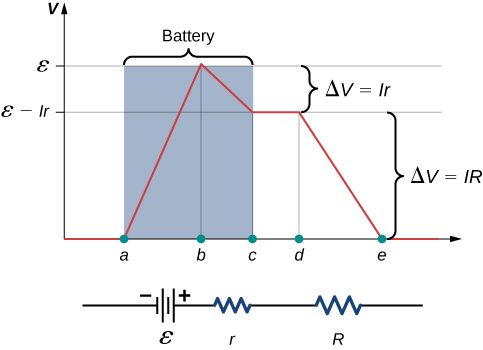
A graph of the potential difference across each element of the circuit is shown in Figure 10.8. A current I runs through the circuit, and the potential drop across the internal resistor is equal to Ir. The terminal voltage is equal to , which is equal to the potential drop across the load resistor . As with potential energy, it is the change in voltage that is important. When the term “voltage” is used, we assume that it is actually the change in the potential, or . However, is often omitted for convenience.
The current through the load resistor is . We see from this expression that the smaller the internal resistance r, the greater the current the voltage source supplies to its load R. As batteries are depleted, r increases. If r becomes a significant fraction of the load resistance, then the current is significantly reduced, as the following example illustrates.
Battery Testers
Battery testers, such as those in Figure 10.9, use small load resistors to intentionally draw current to determine whether the terminal potential drops below an acceptable level. A weak battery has a high internal resistance, resulting in a low terminal voltage.
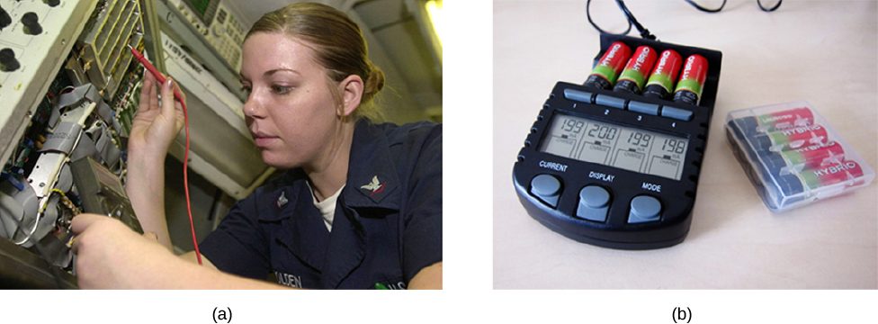
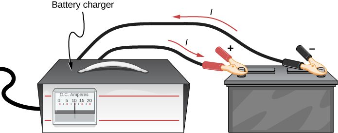
Some batteries can be recharged by passing a current through them in the direction opposite to the current they supply to an appliance. This is done routinely in cars and in batteries for small electrical appliances and electronic devices (Figure 10.10). The voltage output of the battery charger must be greater than the emf of the battery to reverse the current through it. This causes the terminal voltage of the battery to be greater than the emf, since and I is now negative.
It is important to understand the consequences of the internal resistance of emf sources, such as batteries and solar cells, but often, the analysis of circuits is done with the terminal voltage of the battery, as we have done in the previous sections. The terminal voltage is referred to simply as V, dropping the subscript “terminal.” This is because the internal resistance of the battery is difficult to measure directly and can change over time.
Summary
- All voltage sources have two fundamental parts: a source of electrical energy that has a characteristic electromotive force (emf), and an internal resistance r. The emf is the work done per charge to keep the potential difference of a source constant. The emf is equal to the potential difference across the terminals when no current is flowing. The internal resistance r of a voltage source affects the output voltage when a current flows.
- The voltage output of a device is called its terminal voltage and is given by , where I is the electric current and is positive when flowing away from the positive terminal of the voltage source and r is the internal resistance.
Conceptual Questions
What effect will the internal resistance of a rechargeable battery have on the energy being used to recharge the battery?
Some of the energy being used to recharge the battery will be dissipated as heat by the internal resistance.
A battery with an internal resistance of r and an emf of 10.00 V is connected to a load resistor . As the battery ages, the internal resistance triples. How much is the current through the load resistor reduced?
Show that the power dissipated by the load resistor is maximum when the resistance of the load resistor is equal to the internal resistance of the battery.
Problems
A car battery with a 12-V emf and an internal resistance of is being charged with a current of 60 A. Note that in this process, the battery is being charged. (a) What is the potential difference across its terminals? (b) At what rate is thermal energy being dissipated in the battery? (c) At what rate is electric energy being converted into chemical energy?
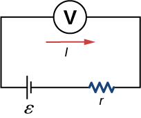
The label on a battery-powered radio recommends the use of a rechargeable nickel-cadmium cell (nicads), although it has a 1.25-V emf, whereas an alkaline cell has a 1.58-V emf. The radio has a resistance. (a) Draw a circuit diagram of the radio and its battery. Now, calculate the power delivered to the radio (b) when using a nicad cells, each having an internal resistance of , and (c) when using an alkaline cell, having an internal resistance of . (d) Does this difference seem significant, considering that the radio’s effective resistance is lowered when its volume is turned up?
a.
b. 0.476W; c. 0.691 W; d. As is lowered, the power difference decreases; therefore, at higher volumes, there is no significant difference.
An automobile starter motor has an equivalent resistance of and is supplied by a 12.0-V battery with a internal resistance. (a) What is the current to the motor? (b) What voltage is applied to it? (c) What power is supplied to the motor? (d) Repeat these calculations for when the battery connections are corroded and add to the circuit. (Significant problems are caused by even small amounts of unwanted resistance in low-voltage, high-current applications.)
(a) What is the internal resistance of a voltage source if its terminal potential drops by 2.00 V when the current supplied increases by 5.00 A? (b) Can the emf of the voltage source be found with the information supplied?
a. ; b. No, there is only one independent equation, so only r can be found.
A person with body resistance between their hands of accidentally grasps the terminals of a 20.0-kV power supply. (Do NOT do this!) (a) Draw a circuit diagram to represent the situation. (b) If the internal resistance of the power supply is , what is the current through their body? (c) What is the power dissipated in their body? (d) If the power supply is to be made safe by increasing its internal resistance, what should the internal resistance be for the maximum current in this situation to be 1.00 mA or less? (e) Will this modification compromise the effectiveness of the power supply for driving low-resistance devices? Explain your reasoning.
A 12.0-V emf automobile battery has a terminal voltage of 16.0 V when being charged by a current of 10.0 A. (a) What is the battery’s internal resistance? (b) What power is dissipated inside the battery? (c) At what rate (in ) will its temperature increase if its mass is 20.0 kg and it has a specific heat of , assuming no heat escapes?
a. ; b. 40.0 W; c.
Adapted from University Physics Volume 2 by OpenStax (openstax.org), licensed under CC BY-NC-SA 4.0. Changes were made. License: CC-BY-NC-SA-4.0.