
9.4 Ohm's Law
We have been discussing three electrical properties so far in this chapter: current, voltage, and resistance. It turns out that many materials exhibit a simple relationship among the values for these properties, known as Ohm’s law. Many other materials do not show this relationship, so despite being called Ohm’s law, it is not considered a law of nature, like Newton’s laws or the laws of thermodynamics. But it is very useful for calculations involving materials that do obey Ohm’s law.
Description of Ohm’s Law
The current that flows through most substances is directly proportional to the voltage V applied to it. The German physicist Georg Simon Ohm (1787–1854) was the first to demonstrate experimentally that the current in a metal wire is directly proportional to the voltage applied:
This important relationship is the basis for Ohm’s law. It can be viewed as a cause-and-effect relationship, with voltage the cause and current the effect. This is an empirical law, which is to say that it is an experimentally observed phenomenon, like friction. Such a linear relationship doesn’t always occur. Any material, component, or device that obeys Ohm’s law, where the current through the device is proportional to the voltage applied, is known as an ohmic material or ohmic component. Any material or component that does not obey Ohm’s law is known as a nonohmic material or nonohmic component.
Ohm’s Experiment
In a paper published in 1827, Georg Ohm described an experiment in which he measured voltage across and current through various simple electrical circuits containing various lengths of wire. A similar experiment is shown in Figure 9.19. This experiment is used to observe the current through a resistor that results from an applied voltage. In this simple circuit, a resistor is connected in series with a battery. The voltage is measured with a voltmeter, which must be placed across the resistor (in parallel with the resistor). The current is measured with an ammeter, which must be in line with the resistor (in series with the resistor).
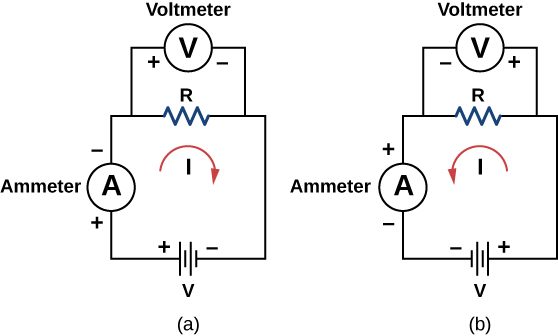
In this updated version of Ohm’s original experiment, several measurements of the current were made for several different voltages. When the battery was hooked up as in Figure 9.19(a), the current flowed in the clockwise direction and the readings of the voltmeter and ammeter were positive. Does the behavior of the current change if the current flowed in the opposite direction? To get the current to flow in the opposite direction, the leads of the battery can be switched. When the leads of the battery were switched, the readings of the voltmeter and ammeter readings were negative because the current flowed in the opposite direction, in this case, counterclockwise. Results of a similar experiment are shown in Figure 9.20.
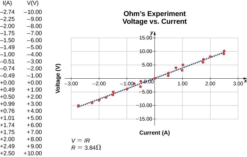
In this experiment, the voltage applied across the resistor varies from −10.00 to +10.00 V, by increments of 1.00 V. The current through the resistor and the voltage across the resistor are measured. A plot is made of the voltage versus the current, and the result is approximately linear. The slope of the line is the resistance, or the voltage divided by the current. This result is known as Ohm’s law:
where V is the voltage measured in volts across the object in question, I is the current measured through the object in amps, and R is the resistance in units of ohms. As stated previously, any device that shows a linear relationship between the voltage and the current is known as an ohmic device. A resistor is therefore an ohmic device.
Nonohmic devices do not exhibit a linear relationship between the voltage and the current. One such device is the semiconducting circuit element known as a diode. A diode is a circuit device that allows current flow in only one direction. A diagram of a simple circuit consisting of a battery, a diode, and a resistor is shown in Figure 9.21. Although we do not cover the theory of the diode in this section, the diode can be tested to see if it is an ohmic or a nonohmic device.
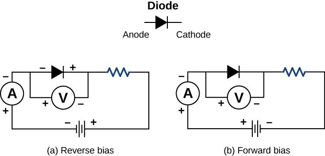
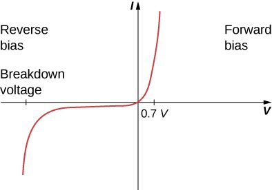
A plot of current versus voltage is shown in Figure 9.22. Note that the behavior of the diode is shown as current versus voltage, whereas the resistor operation was shown as voltage versus current. A diode consists of an anode and a cathode. When the anode is at a negative potential and the cathode is at a positive potential, as shown in part (a), the diode is said to have reverse bias. With reverse bias, the diode has an extremely large resistance and there is very little current flow—essentially zero current—through the diode and the resistor. As the voltage applied to the circuit increases, the current remains essentially zero, until the voltage reaches the breakdown voltage and the diode conducts current, as shown in Figure 9.22. When the battery and the potential across the diode are reversed, making the anode positive and the cathode negative, the diode conducts and current flows through the diode if the voltage is greater than 0.7 V. The resistance of the diode is close to zero. (This is the reason for the resistor in the circuit; if it were not there, the current would become very large.) You can see from the graph in Figure 9.22 that the voltage and the current do not have a linear relationship. Thus, the diode is an example of a nonohmic device.
Ohm’s law is commonly stated as , but originally it was stated as a microscopic view, in terms of the current density, the conductivity, and the electrical field. This microscopic view suggests the proportionality comes from the drift velocity of the free electrons in the metal that results from an applied electrical field. As stated earlier, the current density is proportional to the applied electrical field. The reformulation of Ohm’s law is credited to Gustav Kirchhoff, whose name we will see again in the next chapter.
Summary
- Ohm’s law is an empirical relationship for current, voltage, and resistance for some common types of circuit elements, including resistors. It does not apply to other devices, such as diodes.
- One statement of Ohm’s law gives the relationship among current I, voltage V, and resistance R in a simple circuit as .
- Another statement of Ohm’s law, on a microscopic level, is .
Conceptual Questions
In Determining Field from Potential, resistance was defined as . In this section, we presented Ohm’s law, which is commonly expressed as . The equations look exactly alike. What is the difference between Ohm’s law and the definition of resistance?
Shown below are the results of an experiment where four devices were connected across a variable voltage source. The voltage is increased and the current is measured. Which device, if any, is an ohmic device?
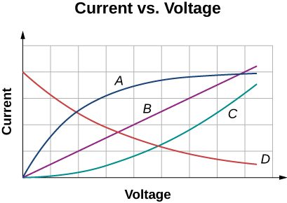
Device B shows a linear relationship and the device is ohmic.
The current I is measured through a sample of an ohmic material as a voltage V is applied. (a) What is the current when the voltage is doubled to 2V (assume the change in temperature of the material is negligible)? (b) What is the voltage applied is the current measured is 0.2I (assume the change in temperature of the material is negligible)? What will happen to the current if the material if the voltage remains constant, but the temperature of the material increases significantly?
Problems
A resistor is connected across a D cell battery (1.5 V). What is the current through the resistor?
A resistor rated at is connected across two D cell batteries (each 1.50 V) in series, with a total voltage of 3.00 V. The manufacturer advertises that their resistors are within 5% of the rated value. What are the possible minimum current and maximum current through the resistor?
A resistor is connected in series with a power supply of 20.00 V. The current measure is 0.50 A. What is the resistance of the resistor?
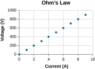
A resistor is placed in a circuit with an adjustable voltage source. The voltage across and the current through the resistor and the measurements are shown below. Estimate the resistance of the resistor.
The following table show the measurements of a current through and the voltage across a sample of material. Plot the data, and assuming the object is an ohmic device, estimate the resistance.
| I(A) | V(V) |
|---|---|
| 0 | 3 |
| 2 | 23 |
| 4 | 39 |
| 6 | 58 |
| 8 | 77 |
| 10 | 100 |
| 12 | 119 |
| 14 | 142 |
| 16 | 162 |
Adapted from University Physics Volume 2 by OpenStax (openstax.org), licensed under CC BY-NC-SA 4.0. Changes were made. License: CC-BY-NC-SA-4.0.