
9.3 Resistivity and Resistance
What drives current? We can think of various devices—such as batteries, generators, wall outlets, and so on—that are necessary to maintain a current. All such devices create a potential difference and are referred to as voltage sources. When a voltage source is connected to a conductor, it applies a potential difference V that creates an electrical field. The electrical field, in turn, exerts force on free charges, causing current. The amount of current depends not only on the magnitude of the voltage, but also on the characteristics of the material that the current is flowing through. The material can resist the flow of the charges, and the measure of how much a material resists the flow of charges is known as the resistivity. This resistivity is crudely analogous to the friction between two materials that resists motion.
Resistivity
When a voltage is applied to a conductor, an electrical field is created, and charges in the conductor feel a force due to the electrical field. The current density that results depends on the electrical field and the properties of the material. This dependence can be very complex. In some materials, including metals at a given temperature, the current density is approximately proportional to the electrical field. In these cases, the current density can be modeled as
where is the electrical conductivity. The electrical conductivity is analogous to thermal conductivity and is a measure of a material’s ability to conduct or transmit electricity. Conductors have a higher electrical conductivity than insulators. Since the electrical conductivity is , the units are
Here, we define a unit named the ohm with the Greek symbol uppercase omega, . The unit is named after Georg Simon Ohm, whom we will discuss later in this chapter. The is used to avoid confusion with the number 0. One ohm equals one volt per amp: . The units of electrical conductivity are therefore .
Conductivity is an intrinsic property of a material. Another intrinsic property of a material is the resistivity, or electrical resistivity. The resistivity of a material is a measure of how strongly a material opposes the flow of electrical current. The symbol for resistivity is the lowercase Greek letter rho, , and resistivity is the reciprocal of electrical conductivity:
The unit of resistivity in SI units is the ohm-meter . We can define the resistivity in terms of the electrical field and the current density,
The greater the resistivity, the larger the field needed to produce a given current density. The lower the resistivity, the larger the current density produced by a given electrical field. Good conductors have a high conductivity and low resistivity. Good insulators have a low conductivity and a high resistivity. Table 9.1 lists resistivity and conductivity values for various materials.
| Material | Conductivity, | Resistivity, | Temperature Coefficient, |
|---|---|---|---|
| Conductors | |||
| Silver | 0.0038 | ||
| Copper | 0.0039 | ||
| Gold | 0.0034 | ||
| Aluminum | 0.0039 | ||
| Tungsten | 0.0045 | ||
| Iron | 0.0065 | ||
| Platinum | 0.0039 | ||
| Steel | |||
| Lead | |||
| Manganin (Cu, Mn, Ni alloy) | 0.000002 | ||
| Constantan (Cu, Ni alloy) | 0.00003 | ||
| Mercury | 0.0009 | ||
| Nichrome (Ni, Fe, Cr alloy) | 0.0004 | ||
| Semiconductors[1] | |||
| Carbon (pure) | −0.0005 | ||
| Carbon | −0.0005 | ||
| Germanium (pure) | −0.048 | ||
| Germanium | −0.050 | ||
| Silicon (pure) | 2300 | −0.075 | |
| Silicon | −0.07 | ||
| Insulators | |||
| Amber | |||
| Glass | |||
| Lucite | |||
| Mica | |||
| Quartz (fused) | |||
| Rubber (hard) | |||
| Sulfur | |||
| TeflonTM | |||
| Wood |
The materials listed in the table are separated into categories of conductors, semiconductors, and insulators, based on broad groupings of resistivity. Conductors have the smallest resistivity, and insulators have the largest; semiconductors have intermediate resistivity. Conductors have varying but large, free charge densities, whereas most charges in insulators are bound to atoms and are not free to move. Semiconductors are intermediate, having far fewer free charges than conductors, but having properties that make the number of free charges depend strongly on the type and amount of impurities in the semiconductor. These unique properties of semiconductors are put to use in modern electronics, as we will explore in later chapters.
Temperature Dependence of Resistivity
Looking back at Table 9.1, you will see a column labeled “Temperature Coefficient.” The resistivity of some materials has a strong temperature dependence. In some materials, such as copper, the resistivity increases with increasing temperature. In fact, in most conducting metals, the resistivity increases with increasing temperature. The increasing temperature causes increased vibrations of the atoms in the lattice structure of the metals, which impede the motion of the electrons. In other materials, such as carbon, the resistivity decreases with increasing temperature. In many materials, the dependence is approximately linear and can be modeled using a linear equation:
where is the resistivity of the material at temperature T, is the temperature coefficient of the material, and is the resistivity at , usually taken as .
Note also that the temperature coefficient is negative for the semiconductors listed in Table 9.1, meaning that their resistivity decreases with increasing temperature. They become better conductors at higher temperature, because increased thermal agitation increases the number of free charges available to carry current. This property of decreasing with temperature is also related to the type and amount of impurities present in the semiconductors.
Resistance
We now consider the resistance of a wire or component. The resistance is a measure of how difficult it is to pass current through a wire or component. Resistance depends on the resistivity. The resistivity is a characteristic of the material used to fabricate a wire or other electrical component, whereas the resistance is a characteristic of the wire or component.
To calculate the resistance, consider a section of conducting wire with cross-sectional area A, length L, and resistivity A battery is connected across the conductor, providing a potential difference across it (Figure 9.13). The potential difference produces an electrical field that is proportional to the current density, according to .
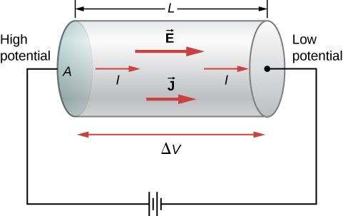
The magnitude of the electrical field across the segment of the conductor is equal to the voltage divided by the length, , and the magnitude of the current density is equal to the current divided by the cross-sectional area, As with capacitance, we use V to represent the potential difference ΔV across the resistor. Using this information and recalling that the electrical field is proportional to the resistivity and the current density, we can see that the voltage is proportional to the current:
The unit of resistance is the ohm, . For a given voltage, the higher the resistance, the lower the current.
Resistors
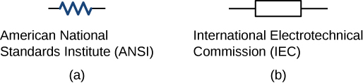
A common component in electronic circuits is the resistor. The resistor can be used to reduce current flow or provide a voltage drop. Figure 9.14 shows the symbols used for a resistor in schematic diagrams of a circuit. Two commonly used standards for circuit diagrams are provided by the American National Standard Institute (ANSI, pronounced “AN-see”) and the International Electrotechnical Commission (IEC). Both systems are commonly used. We use the ANSI standard in this text for its visual recognition, but we note that for larger, more complex circuits, the IEC standard may have a cleaner presentation, making it easier to read.
Material and shape dependence of resistance
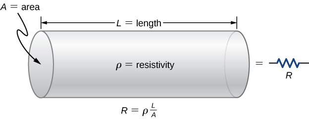
A resistor can be modeled as a cylinder with a cross-sectional area A and a length L, made of a material with a resistivity (Figure 9.15). The resistance of the resistor is .
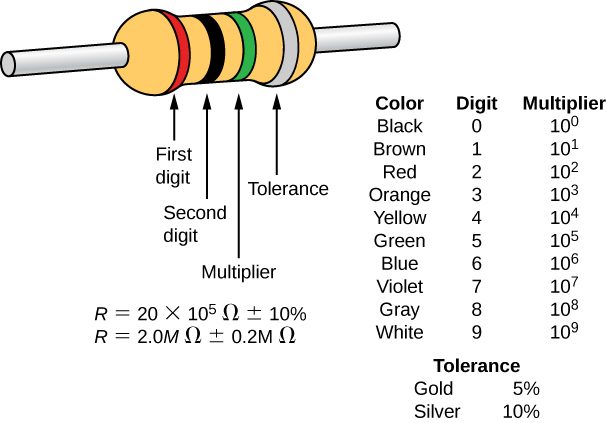
The most common material used to make a resistor is carbon. A carbon track is wrapped around a ceramic core, and two copper leads are attached. A second type of resistor is the metal film resistor, which also has a ceramic core. The track is made from a metal oxide material, which has semiconductive properties similar to carbon. Again, copper leads are inserted into the ends of the resistor. The resistor is then painted and marked for identification. A resistor has four colored bands, as shown in Figure 9.16.
Resistances range over many orders of magnitude. Some ceramic insulators, such as those used to support power lines, have resistances of or more. A dry person may have a hand-to-foot resistance of , whereas the resistance of the human heart is about . A meter-long piece of large-diameter copper wire may have a resistance of , and superconductors have no resistance at all at low temperatures. As we have seen, resistance is related to the shape of an object and the material of which it is composed.
The resistance of an object also depends on temperature, since is directly proportional to For a cylinder, we know , so if L and A do not change greatly with temperature, R has the same temperature dependence as (Examination of the coefficients of linear expansion shows them to be about two orders of magnitude less than typical temperature coefficients of resistivity, so the effect of temperature on L and A is about two orders of magnitude less than on Thus,
is the temperature dependence of the resistance of an object, where is the original resistance (usually taken to be and R is the resistance after a temperature change The color code gives the resistance of the resistor at a temperature of .
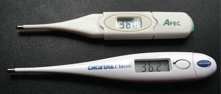
Numerous thermometers are based on the effect of temperature on resistance (Figure 9.17). One of the most common thermometers is based on the thermistor, a semiconductor crystal with a strong temperature dependence, the resistance of which is measured to obtain its temperature. The device is small, so that it quickly comes into thermal equilibrium with the part of a person it touches.
Summary
- Resistance has units of ohms , related to volts and amperes by .
- The resistance R of a cylinder of length L and cross-sectional area A is , where is the resistivity of the material.
- Values of in Table 9.1 show that materials fall into three groups—conductors, semiconductors, and insulators.
- Temperature affects resistivity; for relatively small temperature changes , resistivity is , where is the original resistivity and is the temperature coefficient of resistivity.
- The resistance R of an object also varies with temperature: , where is the original resistance, and R is the resistance after the temperature change.
Conceptual Questions
The IR drop across a resistor means that there is a change in potential or voltage across the resistor. Is there any change in current as it passes through a resistor? Explain.
Do impurities in semiconducting materials listed in Table 9.1 supply free charges? (Hint: Examine the range of resistivity for each and determine whether the pure semiconductor has the higher or lower conductivity.)
In carbon, resistivity increases with the amount of impurities, meaning fewer free charges. In silicon and germanium, impurities decrease resistivity, meaning more free electrons.
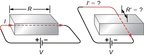
Does the resistance of an object depend on the path current takes through it? Consider, for example, a rectangular bar—is its resistance the same along its length as across its width?
If aluminum and copper wires of the same length have the same resistance, which has the larger diameter? Why?
Copper has a lower resistivity than aluminum, so if length is the same, copper must have the smaller diameter.
Problems
What current flows through the bulb of a 3.00-V flashlight when its hot resistance is ?
Calculate the effective resistance of a pocket calculator that has a 1.35-V battery and through which 0.200 mA flows.
How many volts are supplied to operate an indicator light on a DVD player that has a resistance of , given that 25.0 mA passes through it?
What is the resistance of a 20.0-m-long piece of 12-gauge copper wire having a 2.053-mm diameter?
The diameter of 0-gauge copper wire is 8.252 mm. Find the resistance of a 1.00-km length of such wire used for power transmission.
If the 0.100-mm-diameter tungsten filament in a light bulb is to have a resistance of at , how long should it be?
A lead rod has a length of 30.00 cm and a resistance of . What is the radius of the rod?
Find the ratio of the diameter of aluminum to copper wire, if they have the same resistance per unit length (as they might in household wiring).
What current flows through a 2.54-cm-diameter rod of pure silicon that is 20.0 cm long, when is applied to it? (Such a rod may be used to make nuclear-particle detectors, for example.)
(a) To what temperature must you raise a copper wire, originally at , to double its resistance, neglecting any changes in dimensions? (b) Does this happen in household wiring under ordinary circumstances?
a. ;
b. Under normal conditions, no it should not occur.
A resistor made of nichrome wire is used in an application where its resistance cannot change more than 1.00% from its value at . Over what temperature range can it be used?
Of what material is a resistor made if its resistance is 40.0% greater at than at ?
, tungsten
An electronic device designed to operate at any temperature in the range from to contains pure carbon resistors. By what factor does their resistance increase over this range?
(a) Of what material is a wire made, if it is 25.0 m long with a diameter of 0.100 mm and has a resistance of at ? (b) What is its resistance at
a. , gold;
b.
Assuming a constant temperature coefficient of resistivity, what is the maximum percent decrease in the resistance of a constantan wire starting at and reaching 0 K?
A copper wire has a resistance of at and an iron wire has a resistance of at the same temperature. At what temperature are their resistances equal?
Adapted from University Physics Volume 2 by OpenStax (openstax.org), licensed under CC BY-NC-SA 4.0. Changes were made. License: CC-BY-NC-SA-4.0.