
4.3 Double-Slit Diffraction
When we studied interference in Young’s double-slit experiment, we ignored the diffraction effect in each slit. We assumed that the slits were so narrow that on the screen you saw only the interference of light from just two point sources. If the slit is smaller than the wavelength, then Figure 4.10(a) shows that there is just a spreading of light and no peaks or troughs on the screen. Therefore, it was reasonable to leave out the diffraction effect in that chapter. However, if you make the slit wider, Figure 4.10(b) and (c) show that you cannot ignore diffraction. In this section, we study the complications to the double-slit experiment that arise when you also need to take into account the diffraction effect of each slit.
To calculate the diffraction pattern for two (or any number of) slits, we need to generalize the method we just used for a single slit. That is, across each slit, we place a uniform distribution of point sources that radiate Huygens wavelets, and then we sum the wavelets from all the slits. This gives the intensity at any point on the screen. Although the details of that calculation can be complicated, the final result is quite simple:
In other words, the locations of the interference fringes are given by the equation , the same as when we considered the slits to be point sources, but the intensities of the fringes are now reduced by diffraction effects, according to Equation 4.4. [Note that in the chapter on interference, we wrote and used the integer m to refer to interference fringes. Equation 4.1 also uses m, but this time to refer to diffraction minima. If both equations are used simultaneously, it is good practice to use a different variable (such as n) for one of these integers in order to keep them distinct.]
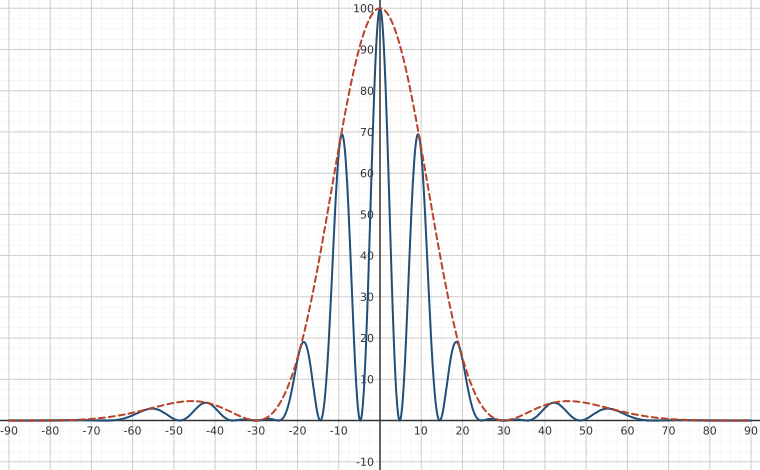
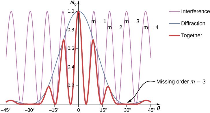
Interference and diffraction effects operate simultaneously and generally produce minima at different angles. This gives rise to a complicated pattern on the screen, in which some of the maxima of interference from the two slits are missing if the maximum of the interference is in the same direction as the minimum of the diffraction. We refer to such a missing peak as a missing order. One example of a diffraction pattern on the screen is shown in Figure 4.11. The solid line with multiple peaks of various heights is the intensity observed on the screen. It is a product of the interference pattern of waves from separate slits and the diffraction of waves from within one slit.
Summary
- With real slits with finite widths, the effects of interference and diffraction operate simultaneously to form a complicated intensity pattern.
- Relative intensities of interference fringes within a diffraction pattern can be determined.
- Missing orders occur when an interference maximum and a diffraction minimum are located together.
Conceptual Questions
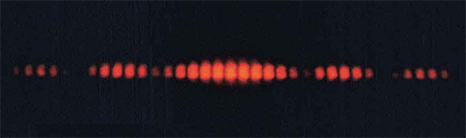
Shown below is the central part of the interference pattern for a pure wavelength of red light projected onto a double slit. The pattern is actually a combination of single- and double-slit interference. Note that the bright spots are evenly spaced. Is this a double- or single-slit characteristic? Note that some of the bright spots are dim on either side of the center. Is this a single- or double-slit characteristic? Which is smaller, the slit width or the separation between slits? Explain your responses.
Problems
Two slits of width each in an opaque material, are separated by a center-to-center distance of A monochromatic light of wavelength 450 nm is incident on the double-slit. One finds a combined interference and diffraction pattern on the screen.
(a) How many peaks of the interference will be observed in the central maximum of the diffraction pattern?
(b) How many peaks of the interference will be observed if the slit width is doubled while keeping the distance between the slits same?
(c) How many peaks of interference will be observed if the slits are separated by twice the distance, that is, while keeping the widths of the slits same?
(d) What will happen in (a) if instead of 450-nm light another light of wavelength 680 nm is used?
(e) What is the value of the ratio of the intensity of the central peak to the intensity of the next bright peak in (a)?
(f) Does this ratio depend on the wavelength of the light?
(g) Does this ratio depend on the width or separation of the slits?
A double slit produces a diffraction pattern that is a combination of single- and double-slit interference. Find the ratio of the width of the slits to the separation between them, if the first minimum of the single-slit pattern falls on the fifth maximum of the double-slit pattern. (This will greatly reduce the intensity of the fifth maximum.)
0.200
For a double-slit configuration where the slit separation is four times the slit width, how many interference fringes lie in the central peak of the diffraction pattern?
Light of wavelength 500 nm falls normally on 50 slits that are wide and spaced apart. How many interference fringes lie in the central peak of the diffraction pattern?
3
A monochromatic light of wavelength 589 nm incident on a double slit with slit width and unknown separation results in a diffraction pattern containing nine interference peaks inside the central maximum. Find the separation of the slits.
When a monochromatic light of wavelength 430 nm incident on a double slit of slit separation , there are 11 interference fringes in its central maximum. How many interference fringes will be in the central maximum of a light of the same wavelength and slit widths, but a new slit separation of ?
9
Determine the intensities of two interference peaks other than the central peak in the central maximum of the diffraction, if possible, when a light of wavelength 628 nm is incident on a double slit of width 500 nm and separation 1500 nm. Use the intensity of the central spot to be .
Adapted from University Physics Volume 3 by OpenStax (openstax.org), licensed under CC BY-NC-SA 4.0. Changes were made. License: CC-BY-NC-SA-4.0.