
3.4 Interference in Thin Films
The bright colors seen in an oil slick floating on water or in a sunlit soap bubble are caused by interference. The brightest colors are those that interfere constructively. This interference is between light reflected from different surfaces of a thin film; thus, the effect is known as thin-film interference. Its effects and applications are everywhere: in incredibly precise optical devices, anti-forgery measures, and in cameras and projectors. As described below, Katharine Burr Blodgett's pioneering invention of nonreflective glass, which utilized the principles of thin-film interference, led to a revolution in movie making.
As we noted before, interference effects are most prominent when light interacts with something having a size similar to its wavelength. A thin film is one having a thickness t smaller than a few times the wavelength of light, . Since color is associated indirectly with and because all interference depends in some way on the ratio of to the size of the object involved, we should expect to see different colors for different thicknesses of a film, as in Figure 3.11.
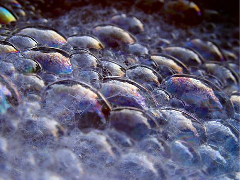
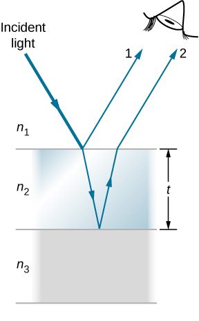
What causes thin-film interference? Figure 3.12 shows how light reflected from the top and bottom surfaces of a film can interfere. Incident light is only partially reflected from the top surface of the film (ray 1). The remainder enters the film and is itself partially reflected from the bottom surface. Part of the light reflected from the bottom surface can emerge from the top of the film (ray 2) and interfere with light reflected from the top (ray 1). The ray that enters the film travels a greater distance, so it may be in or out of phase with the ray reflected from the top. However, consider for a moment, again, the bubbles in Figure 3.11. The bubbles are darkest where they are thinnest. Furthermore, if you observe a soap bubble carefully, you will note it gets dark at the point where it breaks. For very thin films, the difference in path lengths of rays 1 and 2 in Figure 3.12 is negligible, so why should they interfere destructively and not constructively? The answer is that a phase change can occur upon reflection, as discussed next.
Changes in Phase due to Reflection
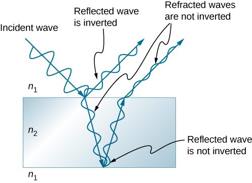
We saw earlier (Waves) that reflection of mechanical waves can involve a phase change. For example, a traveling wave on a string is inverted (i.e., a phase change) upon reflection at a boundary to which a heavier string is tied. However, if the second string is lighter (or more precisely, of a lower linear density), no inversion occurs. Light waves produce the same effect, but the deciding parameter for light is the index of refraction. Light waves undergo a or radians phase change upon reflection at an interface beyond which is a medium of higher index of refraction. No phase change takes place when reflecting from a medium of lower refractive index (Figure 3.13). Because of the periodic nature of waves, this phase change or inversion is equivalent to in distance travelled, or path length. Both the path length and refractive indices are important factors in thin-film interference.
If the film in Figure 3.12 is a soap bubble (essentially water with air on both sides), then a phase shift of occurs for ray 1 but not for ray 2. Thus, when the film is very thin and the path length difference between the two rays is negligible, they are exactly out of phase, and destructive interference occurs at all wavelengths. Thus, the soap bubble is dark here. The thickness of the film relative to the wavelength of light is the other crucial factor in thin-film interference. Ray 2 in Figure 3.12 travels a greater distance than ray 1. For light incident perpendicular to the surface, ray 2 travels a distance approximately 2t farther than ray 1. When this distance is an integral or half-integral multiple of the wavelength in the medium , where is the wavelength in vacuum and n is the index of refraction), constructive or destructive interference occurs, depending also on whether there is a phase change in either ray.
Thin-film interference has created an entire field of research and industrial applications. Its foundations were laid by Irving Langmuir and Katharine Burr Blodgett, working at General Electric in the 1920s and 1930s. Langmuir had pioneered a method for producing ultra-thin layers on materials. Blodgett built on these practices by creating a method to precisely stack and compress these layers in order to produce a film of a desired thickness and quality. The device they developed became known as the Langmuir-Blodgett trough — expanding on a similar device invented by pioneering surface scientist Agnes Pockels — which is still used in laboratories today. The earliest widely applied use of these principles was non-reflective glass. Blodgett patented the material in 1938, in time for its almost immediate use in the creation of the film Gone With the Wind. The movie is viewed as a tremendous leap forward in cinematography; cameras, microscopes, telescopes, and many other instruments rely on Blodgett's invention, as well.
Combining Path Length Difference with Phase Change
Thin-film interference is most constructive or most destructive when the path length difference for the two rays is an integral or half-integral wavelength. That is, for rays incident perpendicularly,
To know whether interference is constructive or destructive, you must also determine if there is a phase change upon reflection. Thin-film interference thus depends on film thickness, the wavelength of light, and the refractive indices. For white light incident on a film that varies in thickness, you can observe rainbow colors of constructive interference for various wavelengths as the thickness varies.
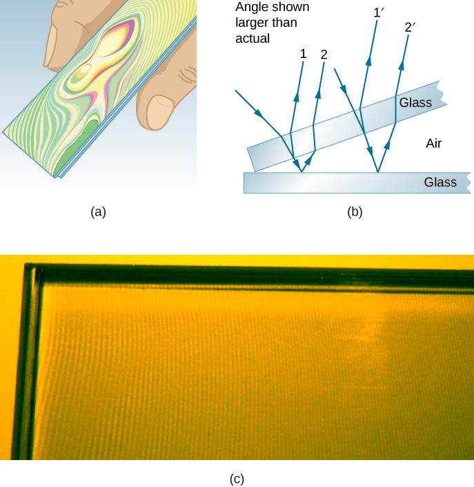
Another example of thin-film interference can be seen when microscope slides are separated (see Figure 3.14). The slides are very flat, so that the wedge of air between them increases in thickness very uniformly. A phase change occurs at the second surface but not the first, so a dark band forms where the slides touch. The rainbow colors of constructive interference repeat, going from violet to red again and again as the distance between the slides increases. As the layer of air increases, the bands become more difficult to see, because slight changes in incident angle have greater effects on path length differences. If monochromatic light instead of white light is used, then bright and dark bands are obtained rather than repeating rainbow colors.
An important application of thin-film interference is found in the manufacturing of optical instruments. A lens or mirror can be compared with a master as it is being ground, allowing it to be shaped to an accuracy of less than a wavelength over its entire surface. Figure 3.15 illustrates the phenomenon called Newton’s rings, which occurs when the plane surfaces of two lenses are placed together. (The circular bands are called Newton’s rings because Isaac Newton described them and their use in detail. Newton did not discover them; Robert Hooke did, and Newton did not believe they were due to the wave character of light.) Each successive ring of a given color indicates an increase of only half a wavelength in the distance between the lens and the blank, so that great precision can be obtained. Once the lens is perfect, no rings appear.
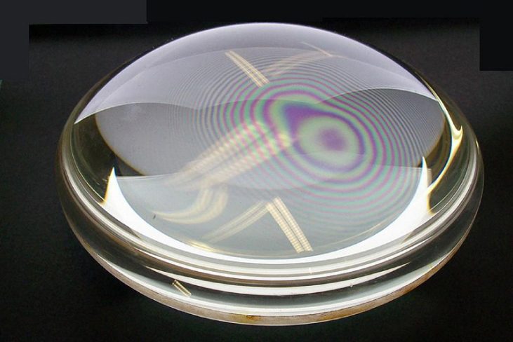
Thin-film interference has many other applications, both in nature and in manufacturing. The wings of certain moths and butterflies have nearly iridescent colors due to thin-film interference. In addition to pigmentation, the wing’s color is affected greatly by constructive interference of certain wavelengths reflected from its film-coated surface. Some car manufacturers offer special paint jobs that use thin-film interference to produce colors that change with angle. This expensive option is based on variation of thin-film path length differences with angle. Security features on credit cards, banknotes, driving licenses, and similar items prone to forgery use thin-film interference, diffraction gratings, or holograms. As early as 1998, Australia led the way with dollar bills printed on polymer with a diffraction grating security feature, making the currency difficult to forge. Other countries, such as Canada, New Zealand, and Taiwan, are using similar technologies, while US currency includes a thin-film interference effect.
Summary
- When light reflects from a medium having an index of refraction greater than that of the medium in which it is traveling, a phase change (or a shift) occurs.
- Thin-film interference occurs between the light reflected from the top and bottom surfaces of a film. In addition to the path length difference, there can be a phase change.
Conceptual Questions
What effect does increasing the wedge angle have on the spacing of interference fringes? If the wedge angle is too large, fringes are not observed. Why?
How is the difference in paths taken by two originally in-phase light waves related to whether they interfere constructively or destructively? How can this be affected by reflection? By refraction?
Differing path lengths result in different phases at destination resulting in constructive or destructive interference accordingly. Reflection can cause a phase change, which also affects how waves interfere. Refraction into another medium changes the wavelength inside that medium such that a wave can emerge from the medium with a different phase compared to another wave that travelled the same distance in a different medium.
Is there a phase change in the light reflected from either surface of a contact lens floating on a person’s tear layer? The index of refraction of the lens is about 1.5, and its top surface is dry.
In placing a sample on a microscope slide, a glass cover is placed over a water drop on the glass slide. Light incident from above can reflect from the top and bottom of the glass cover and from the glass slide below the water drop. At which surfaces will there be a phase change in the reflected light?
Phase changes occur upon reflection at the top of glass cover and the top of glass slide only.
Answer the above question if the fluid between the two pieces of crown glass is carbon disulfide.
While contemplating the food value of a slice of ham, you notice a rainbow of color reflected from its moist surface. Explain its origin.
The surface of the ham being moist means there is a thin layer of fluid, resulting in thin-film interference. Because the exact thickness of the film varies across the piece of ham, which is illuminated by white light, different wavelengths produce bright fringes at different locations, resulting in rainbow colors.
An inventor notices that a soap bubble is dark at its thinnest and realizes that destructive interference is taking place for all wavelengths. How could she use this knowledge to make a nonreflective coating for lenses that is effective at all wavelengths? That is, what limits would there be on the index of refraction and thickness of the coating? How might this be impractical?
A nonreflective coating like the one described in Example 1 works ideally for a single wavelength and for perpendicular incidence. What happens for other wavelengths and other incident directions? Be specific.
Other wavelengths will not generally satisfy for the same value of t so reflections will result in completely destructive interference. For an incidence angle , the path length inside the coating will be increased by a factor so the new condition for destructive interference becomes .
Why is it much more difficult to see interference fringes for light reflected from a thick piece of glass than from a thin film? Would it be easier if monochromatic light were used?
Problems
A soap bubble is 100 nm thick and illuminated by white light incident perpendicular to its surface. What wavelength and color of visible light is most constructively reflected, assuming the same index of refraction as water?
532 nm (green)
An oil slick on water is 120 nm thick and illuminated by white light incident perpendicular to its surface. What color does the oil appear (what is the most constructively reflected wavelength), given its index of refraction is 1.40?
Calculate the minimum thickness of an oil slick on water that appears blue when illuminated by white light perpendicular to its surface. Take the blue wavelength to be 470 nm and the index of refraction of oil to be 1.40.
Find the minimum thickness of a soap bubble that appears red when illuminated by white light perpendicular to its surface. Take the wavelength to be 680 nm, and assume the same index of refraction as water.
A film of soapy water () on top of a plastic cutting board has a thickness of 233 nm. What color is most strongly reflected if it is illuminated perpendicular to its surface?
620 nm (orange)
What are the three smallest non-zero thicknesses of soapy water () on Plexiglas if it appears green (constructively reflecting 520-nm light) when illuminated perpendicularly by white light?
Suppose you have a lens system that is to be used primarily for 700-nm red light. What is the second thinnest coating of fluorite (magnesium fluoride) that would be nonreflective for this wavelength?
380 nm
(a) As a soap bubble thins it becomes dark, because the path length difference becomes small compared with the wavelength of light and there is a phase shift at the top surface. If it becomes dark when the path length difference is less than one-fourth the wavelength, what is the thickest the bubble can be and appear dark at all visible wavelengths? Assume the same index of refraction as water. (b) Discuss the fragility of the film considering the thickness found.
To save money on making military aircraft invisible to radar, an inventor decides to coat them with a nonreflective material having an index of refraction of 1.20, which is between that of air and the surface of the plane. This, he reasons, should be much cheaper than designing Stealth bombers. (a) What thickness should the coating be to inhibit the reflection of 4.00-cm wavelength radar? (b) What is unreasonable about this result? (c) Which assumptions are unreasonable or inconsistent?
a. Assuming n for the plane is greater than 1.20, then there are two phase changes: 0.833 cm. b. It is too thick, and the plane would be too heavy. c. It is unreasonable to think the layer of material could be any thickness when used on a real aircraft.
Adapted from University Physics Volume 3 by OpenStax (openstax.org), licensed under CC BY-NC-SA 4.0. Changes were made. License: CC-BY-NC-SA-4.0.