
15.4 Power in an AC Circuit
A circuit element dissipates or produces power according to where I is the current through the element and V is the voltage across it. Since the current and the voltage both depend on time in an ac circuit, the instantaneous power is also time dependent. A plot of p(t) for various circuit elements is shown in Figure 15.16. For a resistor, i(t) and v(t) are in phase and therefore always have the same sign (see Figure 15.5). For a capacitor or inductor, the relative signs of i(t) and v(t) vary over a cycle due to their phase differences (see Figure 15.7 and Figure 15.9). Consequently, p(t) is positive at some times and negative at others, indicating that capacitive and inductive elements produce power at some instants and absorb it at others.
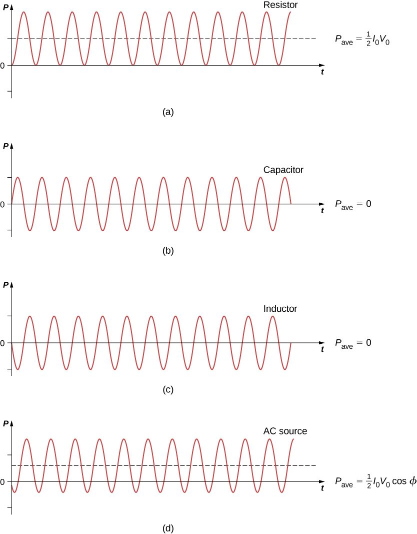
Because instantaneous power varies in both magnitude and sign over a cycle, it seldom has any practical importance. What we’re almost always concerned with is the power averaged over time, which we refer to as the average power. It is defined by the time average of the instantaneous power over one cycle:
where is the period of the oscillations. With the substitutions and this integral becomes
Using the trigonometric relation we obtain
Evaluation of these two integrals yields
and
Hence, the average power associated with a circuit element is given by
In engineering applications, is known as the power factor, which is the amount by which the power delivered in the circuit is less than the theoretical maximum of the circuit due to voltage and current being out of phase. For a resistor, so the average power dissipated is
A comparison of p(t) and is shown in Figure 15.16(d). To make look like its dc counterpart, we use the rms values of the current and the voltage. By definition, these are
where
With we obtain
We may then write for the average power dissipated by a resistor,
This equation further emphasizes why the rms value is chosen in discussion rather than peak values. Both equations for average power are correct for Equation 15.13, but the rms values in the formula give a cleaner representation, so the extra factor of 1/2 is not necessary.
Alternating voltages and currents are usually described in terms of their rms values. For example, the 110 V from a household outlet is an rms value. The amplitude of this source is Because most ac meters are calibrated in terms of rms values, a typical ac voltmeter placed across a household outlet will read 110 V.
For a capacitor and an inductor, respectively. Since we find from Equation 15.12 that the average power dissipated by either of these elements is Capacitors and inductors absorb energy from the circuit during one half-cycle and then discharge it back to the circuit during the other half-cycle. This behavior is illustrated in the plots of Figure 15.16, (b) and (c), which show p(t) oscillating sinusoidally about zero.
The phase angle for an ac generator may have any value. If the generator produces power; if it absorbs power. In terms of rms values, the average power of an ac generator is written as
For the generator in an RLC circuit,
and
Hence the average power of the generator is
This can also be written as
which designates that the power produced by the generator is dissipated in the resistor. As we can see, Ohm’s law for the rms ac is found by dividing the rms voltage by the impedance.
Summary
- The average ac power is found by multiplying the rms values of current and voltage.
- Ohm’s law for the rms ac is found by dividing the rms voltage by the impedance.
- In an ac circuit, there is a phase angle between the source voltage and the current, which can be found by dividing the resistance by the impedance.
- The average power delivered to an RLC circuit is affected by the phase angle.
- The power factor ranges from –1 to 1.
Conceptual Questions
For what value of the phase angle between the voltage output of an ac source and the current is the average power output of the source a maximum?
Discuss the differences between average power and instantaneous power.
The instantaneous power is the power at a given instant. The average power is the power averaged over a cycle or number of cycles.
The average ac current delivered to a circuit is zero. Despite this, power is dissipated in the circuit. Explain.
Can the instantaneous power output of an ac source ever be negative? Can the average power output be negative?
The instantaneous power can be negative, but the power output can’t be negative.
The power rating of a resistor used in ac circuits refers to the maximum average power dissipated in the resistor. How does this compare with the maximum instantaneous power dissipated in the resistor?
Problems
The emf of an ac source is given by where and Calculate the average power output of the source if it is connected across (a) a capacitor, (b) a 20-mH inductor, and (c) a resistor.
Calculate the rms currents for an ac source is given by where and when connected across (a) a capacitor, (b) a 20-mH inductor, and (c) a resistor.
a. 0.89 A; b. 5.6A; c. 1.4 A
A 40-mH inductor is connected to a 60-Hz AC source whose voltage amplitude is 50 V. If an AC voltmeter is placed across the inductor, what does it read?
For an RLC series circuit, the voltage amplitude and frequency of the source are 100 V and 500 Hz, respectively; ; and . Find the average power dissipated in the resistor for the following values for the capacitance: (a) and (b)
a. 5.3 W; b. 2.1 W
An ac source of voltage amplitude 10 V delivers electric energy at a rate of 0.80 W when its current output is 2.5 A. What is the phase angle between the emf and the current?
An RLC series circuit has an impedance of and a power factor of 0.50, with the voltage lagging the current. (a) Should a capacitor or an inductor be placed in series with the elements to raise the power factor of the circuit? (b) What is the value of the reactance across the inductor that will raise the power factor to unity?
a. inductor; b.
Adapted from University Physics Volume 2 by OpenStax (openstax.org), licensed under CC BY-NC-SA 4.0. Changes were made. License: CC-BY-NC-SA-4.0.