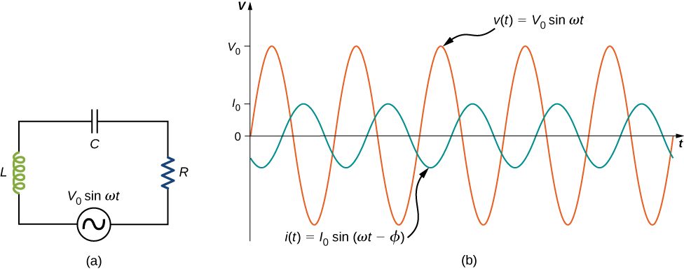
The ac circuit shown in Figure 15.11, called an RLC series circuit, is a series combination of a resistor, capacitor, and inductor connected across an ac source. It produces an emf of
Figure 15.11(a) An RLC series circuit. (b) A comparison of the generator output voltage and the current. The value of the phase difference depends on the values of R, C, and L.
Since the elements are in series, the same current flows through each element at all points in time. The relative phase between the current and the emf is not obvious when all three elements are present. Consequently, we represent the current by the general expression
where is the current amplitude and is the phase angle between the current and the applied voltage. The phase angle is thus the amount by which the voltage and current are out of phase with each other in a circuit. Our task is to find
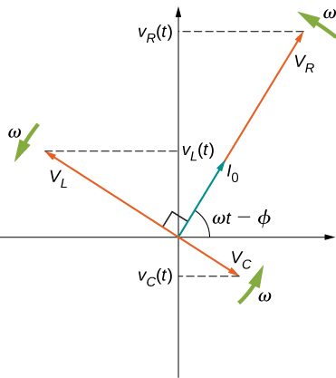
A phasor diagram involving is helpful for analyzing the circuit. As shown in Figure 15.12, the phasor representing points in the same direction as the phasor for its amplitude is The phasor lags the i(t) phasor by rad and has the amplitude The phasor for leads the i(t) phasor by rad and has the amplitude
Figure 15.12The phasor diagram for the RLC series circuit of Figure 15.11.
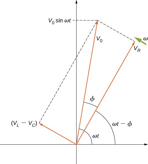
At any instant, the voltage across the RLC combination is the emf of the source. Since a component of a sum of vectors is the sum of the components of the individual vectors—for example, —the projection of the vector sum of phasors onto the vertical axis is the sum of the vertical projections of the individual phasors. Hence, if we add vectorially the phasors representing and then find the projection of the resultant onto the vertical axis, we obtain
The vector sum of the phasors is shown in Figure 15.13. The resultant phasor has an amplitude and is directed at an angle with respect to the or , phasor. The projection of this resultant phasor onto the vertical axis is We can easily determine the unknown quantities and from the geometry of the phasor diagram. For the phase angle,
Interactive figurePhasor amplitudes for the Example 15.2 RLC circuit, with the drive frequency on a sliderDrag the Drive frequency f (the worked example uses 200 Hz) slider from 60 to 400.
XYZ Graph · viewer build 5edf91b
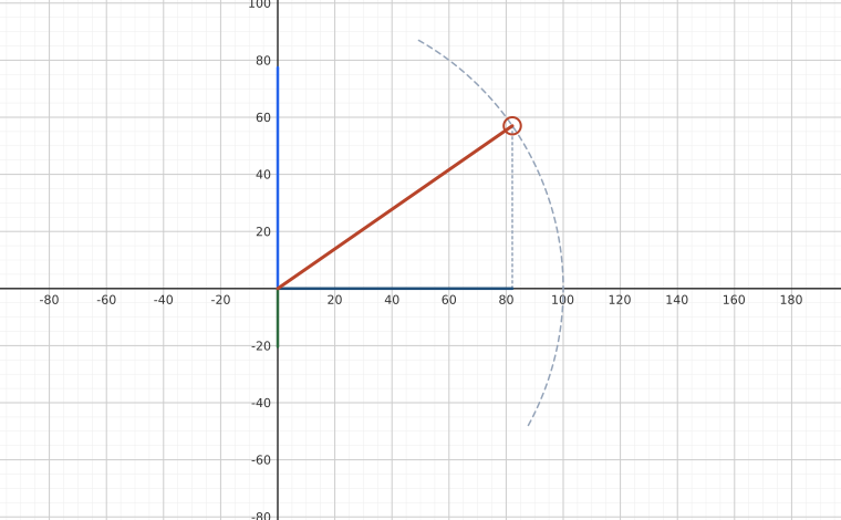
The phasor construction this section builds, for the circuit the example An RLC Series Circuit uses: R = 4.00 Ω, L = 3.00 mH, C = 8.00 × 10⁻⁴ F, driven at amplitude V₀ = 0.100 V. Both axes are voltage in millivolts — the same unit on each, which is what makes the drawn angle the true phase angle. The segments are phasor AMPLITUDES drawn in the frame co-rotating with the current, that is, the snapshot in which the current phasor lies along the horizontal axis; they are not instantaneous voltages, and this section's own figures show the same phasors turned to a general angle ωt with the instantaneous value read off the vertical projection. Fixing the frame to the current removes ωt and leaves every angle between the phasors unchanged, which is what lets the frequency become a slider. At the example's 200 Hz the inductor wins — X_L = 3.77 Ω against X_C = 0.995 Ω — so V_L − V_C points up and the source leads the current by φ = 34.8°, the 0.607 rad the example computes. Drag the frequency down through 102.7 Hz and the diagram flips character: the reactances cancel at resonance, f₀ = 102.7 Hz, where V_R alone carries the whole 100 mV — the 1 Hz slider stops at 103 Hz, close enough that the residual tilt is a fraction of a pixel, and below it the capacitor dominates and the current leads instead. The dashed arc is the reason the picture stays readable: the source amplitude is set by the generator, so the resultant is always 100 mV long and only its angle can change.
and after cancellation of this becomes
(15.9)
Furthermore, from the Pythagorean theorem,
Figure 15.13The resultant of the phasors for , , and is equal to the phasor for The i(t) phasor (not shown) is aligned with the phasor.
The current amplitude is therefore the ac version of Ohm’s law:
(15.10)
where
(15.11)
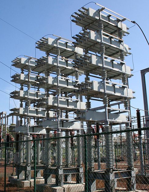
is known as the impedance of the circuit. Its unit is the ohm, and it is the ac analog to resistance in a dc circuit, which measures the combined effect of resistance, capacitive reactance, and inductive reactance (Figure 15.14).
Figure 15.14Power capacitors are used to balance the impedance of the effective inductance in transmission lines.
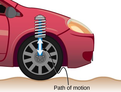
The RLC circuit is analogous to the wheel of a car driven over a corrugated road (Figure 15.15). The regularly spaced bumps in the road drive the wheel up and down; in the same way, a voltage source increases and decreases. The shock absorber acts like the resistance of the RLC circuit, damping and limiting the amplitude of the oscillation. Energy within the wheel system goes back and forth between kinetic and potential energy stored in the car spring, analogous to the shift between a maximum current, with energy stored in an inductor, and no current, with energy stored in the electric field of a capacitor. The amplitude of the wheel’s motion is at a maximum if the bumps in the road are hit at the resonant frequency, which we describe in more detail in Resonance in an AC Circuit.
Figure 15.15On a car, the shock absorber damps motion and dissipates energy. This is much like the resistance in an RLC circuit. The mass and spring determine the resonant frequency.
Summary
An RLC series circuit is a resistor, capacitor, and inductor series combination across an ac source.
The same current flows through each element of an RLC series circuit at all points in time.
The counterpart of resistance in a dc circuit is impedance, which measures the combined effect of resistors, capacitors, and inductors. The maximum current is defined by the ac version of Ohm’s law.
Impedance has units of ohms and is found using the resistance, the capacitive reactance, and the inductive reactance.
Conceptual Questions
In an RLC series circuit, can the voltage measured across the capacitor be greater than the voltage of the source? Answer the same question for the voltage across the inductor.
yes for both
Problems
What is the impedance of a series combination of a resistor, a capacitor, and a capacitor at a frequency of 2.0 kHz?
A resistor and capacitor are connected in series across an ac generator. The emf of the generator is given by where , and . (a) What is the impedance of the circuit? (b) What is the amplitude of the current through the resistor? (c) Write an expression for the current through the resistor. (d) Write expressions representing the voltages across the resistor and across the capacitor.
a. ;
b. 0.16 A;
c. ;
d. ;
A resistor and inductor are connected in series across an ac generator. The emf of the generator is given by where and also, and (a) What is the impedance of the circuit? (b) What is the amplitude of the current through the resistor? (c) Write an expression for the current through the resistor. (d) Write expressions representing the voltages across the resistor and across the inductor.
In an RLC series circuit, the voltage amplitude and frequency of the source are 100 V and 500 Hz, respectively, an and (a) What is the impedance of the circuit? (b) What is the amplitude of the current from the source? (c) If the emf of the source is given by , how does the current vary with time? (d) Repeat the calculations with C changed to
a. ; b. 0.15 A; c. ; d. , 0.092 A,
An RLC series circuit with , and is driven by an ac source whose frequency and voltage amplitude are 500 Hz and 50 V, respectively. (a) What is the impedance of the circuit? (b) What is the amplitude of the current in the circuit? (c) What is the phase angle between the emf of the source and the current?
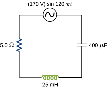
For the circuit shown below, what are (a) the total impedance and (b) the phase angle between the current and the emf? (c) Write an expression for
a. ; b. ; c.
Adapted from University Physics Volume 2 by OpenStax (openstax.org), licensed under CC BY-NC-SA 4.0. Changes were made. License: CC-BY-NC-SA-4.0.
These eBooks are a prerelease and are not yet certified conformant with WCAG 2.1 AA or ADA Title II. Every page is built against an automated accessibility gate, and the published editions will meet ADA Title II requirements when they release in late September 2026. If something is unusable, please tell us.