
13.3 Motional Emf
Magnetic flux depends on three factors: the strength of the magnetic field, the area through which the field lines pass, and the orientation of the field with the surface area. If any of these quantities varies, a corresponding variation in magnetic flux occurs. So far, we’ve only considered flux changes due to a changing field. Now we look at another possibility: a changing area through which the field lines pass including a change in the orientation of the area.
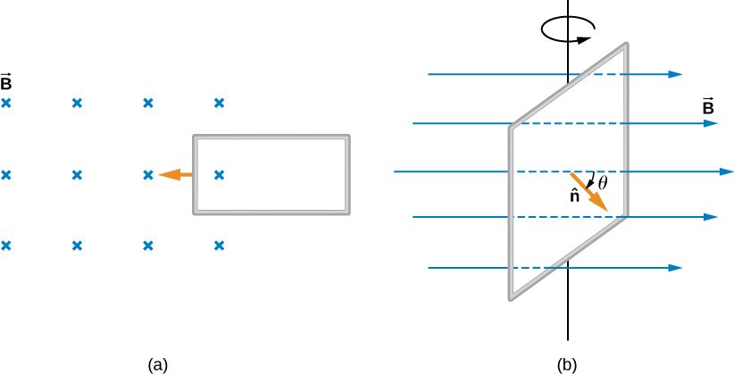
Two examples of this type of flux change are represented in Figure 13.11. In part (a), the flux through the rectangular loop increases as it moves into the magnetic field, and in part (b), the flux through the rotating coil varies with the angle .
Now let’s look at a conducting rod pulled in a circuit, changing magnetic flux. The area enclosed by the circuit ‘MNOP’ of Figure 13.12 is lx and is perpendicular to the magnetic field, so we can simplify the integration of Equation 13.1 into a multiplication of magnetic field and area. The magnetic flux through the open surface is therefore
Since B and l are constant and the velocity of the rod is we can now restate Faraday’s law, Equation 13.2, for the magnitude of the emf in terms of the moving conducting rod as
The current induced in the circuit is the emf divided by the resistance or
Furthermore, the direction of the induced emf satisfies Lenz’s law, as you can verify by inspection of the figure.
This calculation of motionally induced emf is not restricted to a rod moving on conducting rails. With as the starting point, it can be shown that holds for any change in flux caused by the motion of a conductor. We saw in Faraday’s Law that the emf induced by a time-varying magnetic field obeys this same relationship, which is Faraday’s law. Thus Faraday’s law holds for all flux changes, whether they are produced by a changing magnetic field, by motion, or by a combination of the two.
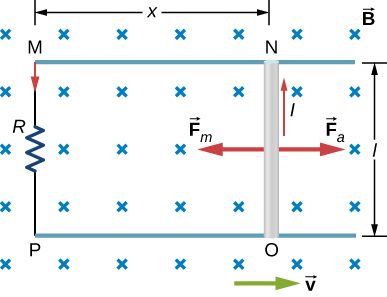
From an energy perspective, produces power and the resistor dissipates power . Since the rod is moving at constant velocity, the applied force must balance the magnetic force on the rod when it is carrying the induced current I. Thus the power produced is
The power dissipated is
In satisfying the principle of energy conservation, the produced and dissipated powers are equal.
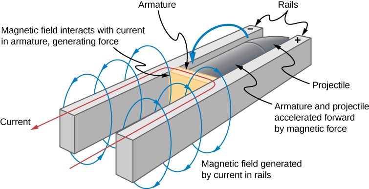
This principle can be seen in the operation of a rail gun. A rail gun is an electromagnetic projectile launcher that uses an apparatus similar to Figure 13.12 and is shown in schematic form in Figure 13.13. The conducting rod is replaced with a projectile or weapon to be fired. So far, we’ve only heard about how motion causes an emf. In a rail gun, the optimal shutting off/ramping down of a magnetic field decreases the flux in between the rails, causing a current to flow in the rod (armature) that holds the projectile. This current through the armature experiences a magnetic force and is propelled forward. Rail guns, however, are not used widely in the military due to the high cost of production and high currents: Nearly one million amps is required to produce enough energy for a rail gun to be an effective weapon.
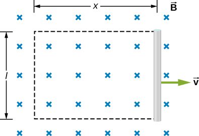
We can calculate a motionally induced emf with Faraday’s law even when an actual closed circuit is not present. We simply imagine an enclosed area whose boundary includes the moving conductor, calculate , and then find the emf from Faraday’s law. For example, we can let the moving rod of Figure 13.14 be one side of the imaginary rectangular area represented by the dashed lines. The area of the rectangle is lx, so the magnetic flux through it is Differentiating this equation, we obtain
which is identical to the potential difference between the ends of the rod that we determined earlier.
Motional emfs in Earth’s weak magnetic field are not ordinarily very large, or we would notice voltage along metal rods, such as a screwdriver, during ordinary motions. For example, a simple calculation of the motional emf of a 1.0-m rod moving at 3.0 m/s perpendicular to the Earth’s field gives
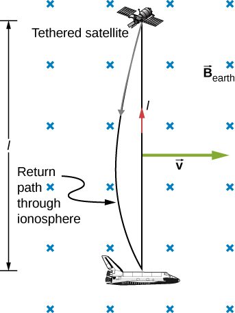
This small value is consistent with experience. There is a spectacular exception, however. In 1992 and 1996, attempts were made with the space shuttle to create large motional emfs. The tethered satellite was to be let out on a 20-km length of wire, as shown in Figure 13.15, to create a 5-kV emf by moving at orbital speed through Earth’s field. This emf could be used to convert some of the shuttle’s kinetic and potential energy into electrical energy if a complete circuit could be made. To complete the circuit, the stationary ionosphere was to supply a return path through which current could flow. (The ionosphere is the rarefied and partially ionized atmosphere at orbital altitudes. It conducts because of the ionization. The ionosphere serves the same function as the stationary rails and connecting resistor in Figure 13.13, without which there would not be a complete circuit.) Drag on the current in the cable due to the magnetic force does the work that reduces the shuttle’s kinetic and potential energy, and allows it to be converted into electrical energy. Both tests were unsuccessful. In the first, the cable hung up and could only be extended a couple of hundred meters; in the second, the cable broke when almost fully extended. Example 1 indicates feasibility in principle.
Summary
- The relationship between an induced emf in a wire moving at a constant speed v through a magnetic field B is given by
- An induced emf from Faraday’s law is created from a motional emf that opposes the change in flux.
Conceptual Questions
A bar magnet falls under the influence of gravity along the axis of a long copper tube. If air resistance is negligible, will there be a force to oppose the descent of the magnet? If so, will the magnet reach a terminal velocity?
Around the geographic North Pole (or magnetic South Pole), Earth’s magnetic field is almost vertical. If an airplane is flying northward in this region, which side of the wing is positively charged and which is negatively charged?
Positive charges on the wings would be to the west, or to the left of the pilot while negative charges would be pulled east or to the right of the pilot. Thus, the left hand tips of the wings would be positive and the right hand tips would be negative.
A wire loop moves translationally (no rotation) in a uniform magnetic field. Is there an emf induced in the loop?
Problems
An automobile with a radio antenna 1.0 m long travels at 100.0 km/h in a location where the Earth’s horizontal magnetic field is What is the maximum possible emf induced in the antenna due to this motion?
0.0015 V
The rectangular loop of N turns shown below moves to the right with a constant velocity while leaving the poles of a large electromagnet. (a) Assuming that the magnetic field is uniform between the pole faces and negligible elsewhere, determine the induced emf in the loop. (b) What is the source of work that produces this emf?
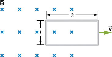
Suppose the magnetic field of the preceding problem oscillates with time according to What then is the emf induced in the loop when its trailing side is a distance d from the right edge of the magnetic field region?
A coil of 1000 turns encloses an area of . It is rotated in 0.010 s from a position where its plane is perpendicular to Earth’s magnetic field to one where its plane is parallel to the field. If the strength of the field is what is the average emf induced in the coil?
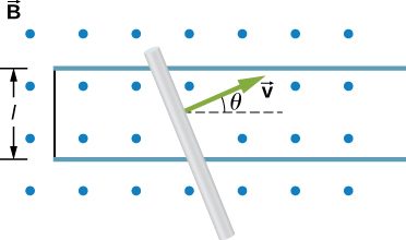
In the circuit shown in the accompanying figure, the rod slides along the conducting rails at a constant velocity The velocity is in the same plane as the rails and directed at an angle to them. A uniform magnetic field is directed out of the page. What is the emf induced in the rod?
The rod shown in the accompanying figure is moving through a uniform magnetic field of strength with a constant velocity of magnitude What is the potential difference between the ends of the rod? Which end of the rod is at a higher potential?
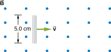
A 25-cm rod moves at 5.0 m/s in a plane perpendicular to a magnetic field of strength 0.25 T. The rod, velocity vector, and magnetic field vector are mutually perpendicular, as indicated in the accompanying figure. Calculate (a) the magnetic force on an electron in the rod, (b) the electric field in the rod, and (c) the potential difference between the ends of the rod. (d) What is the speed of the rod if the potential difference is 1.0 V?
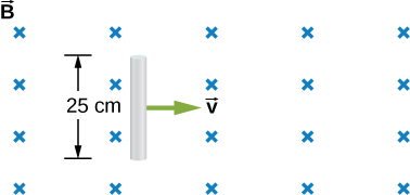
a. ; b. 1.25 V/m; c. 0.3125 V; d. 16 m/s
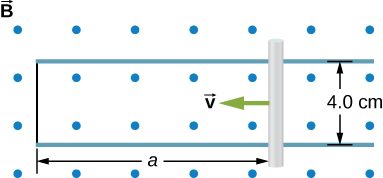
In the accompanying figure, the rails, connecting end piece, and rod all have a resistance per unit length of The rod moves to the left at If everywhere in the region, what is the current in the circuit (a) when (b) when Specify also the sense of the current flow.
The rod shown below moves to the right on essentially zero-resistance rails at a speed of If everywhere in the region, what is the current through the resistor? Does the current circulate clockwise or counterclockwise?
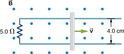
0.018 A, CW as seen in the diagram
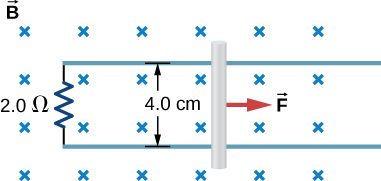
Shown below is a conducting rod that slides along metal rails. The apparatus is in a uniform magnetic field of strength 0.25 T, which is directly into the page. The rod is pulled to the right at a constant speed of 5.0 m/s by a force The only significant resistance in the circuit comes from the resistor shown. (a) What is the emf induced in the circuit? (b) What is the induced current? Does it circulate clockwise or counter clockwise? (c) What is the magnitude of ? (d) What are the power output of and the power dissipated in the resistor?
Adapted from University Physics Volume 2 by OpenStax (openstax.org), licensed under CC BY-NC-SA 4.0. Changes were made. License: CC-BY-NC-SA-4.0.