
13.2 Lenz's Law
The direction in which the induced emf drives current around a wire loop can be found through the negative sign. However, it is usually easier to determine this direction with Lenz’s law, named in honor of its discoverer, Heinrich Lenz (1804–1865). (Faraday also discovered this law, independently of Lenz.) We state Lenz’s law as follows:
Lenz’s law can also be considered in terms of conservation of energy. If pushing a magnet into a coil causes current, the energy in that current must have come from somewhere. If the induced current causes a magnetic field opposing the increase in field of the magnet we pushed in, then the situation is clear. We pushed a magnet against a field and did work on the system, and that showed up as current. If it were not the case that the induced field opposes the change in the flux, the magnet would be pulled in and produce a current without any work. Electric potential energy would have been created, violating the conservation of energy.
To determine an induced emf , you first calculate the magnetic flux and then obtain The magnitude of is given by Finally, you can apply Lenz’s law to determine the sense of . This will be developed through examples that illustrate the following problem-solving strategy.
Let’s apply Lenz’s law to the system of Figure 13.7(a). We designate the “front” of the closed conducting loop as the region containing the approaching bar magnet, and the “back” of the loop as the other region. As the north pole of the magnet moves toward the loop, the flux through the loop due to the field of the magnet increases because the strength of field lines directed from the front to the back of the loop is increasing. A current is therefore induced in the loop. By Lenz’s law, the direction of the induced current must be such that its own magnetic field is directed in a way to oppose the changing flux caused by the field of the approaching magnet. Hence, the induced current circulates so that its magnetic field lines through the loop are directed from the back to the front of the loop. By RHR-2, place your thumb pointing against the magnetic field lines, which is toward the bar magnet. Your fingers wrap in a counterclockwise direction as viewed from the bar magnet. Alternatively, we can determine the direction of the induced current by treating the current loop as an electromagnet that opposes the approach of the north pole of the bar magnet. This occurs when the induced current flows as shown, for then the face of the loop nearer the approaching magnet is also a north pole.
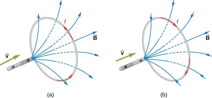
Part (b) of the figure shows the south pole of a magnet moving toward a conducting loop. In this case, the flux through the loop due to the field of the magnet increases because the number of field lines directed from the back to the front of the loop is increasing. To oppose this change, a current is induced in the loop whose field lines through the loop are directed from the front to the back. Equivalently, we can say that the current flows in a direction so that the face of the loop nearer the approaching magnet is a south pole, which then repels the approaching south pole of the magnet. By RHR-2, your thumb points away from the bar magnet. Your fingers wrap in a clockwise fashion, which is the direction of the induced current.
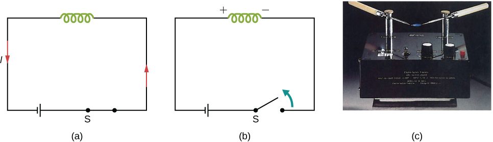
Another example illustrating the use of Lenz’s law is shown in Figure 13.8. When the switch is opened, the decrease in current through the solenoid causes a decrease in magnetic flux through its coils, which induces an emf in the solenoid. This emf must oppose the change (the termination of the current) causing it. Consequently, the induced emf has the polarity shown and drives in the direction of the original current. This may generate an arc across the terminals of the switch as it is opened.
Summary
- We can use Lenz’s law to determine the directions of induced magnetic fields, currents, and emfs.
- The direction of an induced emf always opposes the change in magnetic flux that causes the emf, a result known as Lenz’s law.
Conceptual Questions
The circular conducting loops shown in the accompanying figure are parallel, perpendicular to the plane of the page, and coaxial. (a) When the switch S is closed, what is the direction of the current induced in D? (b) When the switch is opened, what is the direction of the current induced in loop D?
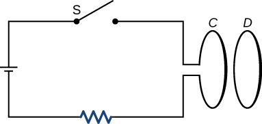
a. CW as viewed from the circuit; b. CCW as viewed from the circuit
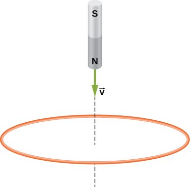
The north pole of a magnet is moved toward a copper loop, as shown below. If you are looking at the loop from above the magnet, will you say the induced current is circulating clockwise or counterclockwise?
The accompanying figure shows a conducting ring at various positions as it moves through a magnetic field. What is the sense of the induced emf for each of those positions?
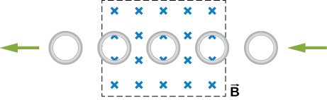
As the loop enters, the induced emf creates a CCW current while as the loop leaves the induced emf creates a CW current. While the loop is fully inside the magnetic field, there is no flux change and therefore no induced current.
Show that and have the same units.
State the direction of the induced current for each case shown below, observing from the side of the magnet.
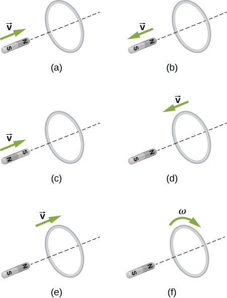
a. CCW viewed from the magnet; b. CW viewed from the magnet; c. CW viewed from the magnet; d. CCW viewed from the magnet; e. CW viewed from the magnet; f. no current
Problems
A single-turn circular loop of wire of radius 50 mm lies in a plane perpendicular to a spatially uniform magnetic field. During a 0.10-s time interval, the magnitude of the field increases uniformly from 200 to 300 mT. (a) Determine the emf induced in the loop. (b) If the magnetic field is directed out of the page, what is the direction of the current induced in the loop?
a. ; b. CCW from the same view as the magnetic field
When a magnetic field is first turned on, the flux through a 20-turn loop varies with time according to where is in milliwebers, t is in seconds, and the loop is in the plane of the page with the unit normal pointing outward. (a) What is the emf induced in the loop as a function of time? What is the direction of the induced current at (b) t = 0, (c) 0.10, (d) 1.0, and (e) 2.0 s?
The magnetic flux through the loop shown in the accompanying figure varies with time according to where is in webers. What are the direction and magnitude of the current through the resistor at (a) ; (b) and (c)
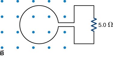
a. 150 A downward through the resistor; b. 46 A upward through the resistor; c. 0.019 A downward through the resistor
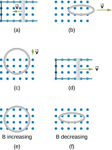
Use Lenz’s law to determine the direction of induced current in each case.
Adapted from University Physics Volume 2 by OpenStax (openstax.org), licensed under CC BY-NC-SA 4.0. Changes were made. License: CC-BY-NC-SA-4.0.