All examples in this chapter are planar problems. Accordingly, we use equilibrium conditions in the component form of Equation 12.7 to Equation 12.9. We introduced a problem-solving strategy in Example 1 in Section 12.1 to illustrate the physical meaning of the equilibrium conditions. Now we generalize this strategy in a list of steps to follow when solving static equilibrium problems for extended rigid bodies. We proceed in five practical steps.
Note that setting up a free-body diagram for a rigid-body equilibrium problem is the most important component in the solution process. Without the correct setup and a correct diagram, you will not be able to write down correct conditions for equilibrium. Also note that a free-body diagram for an extended rigid body that may undergo rotational motion is different from a free-body diagram for a body that experiences only translational motion (as you saw in the chapters on Newton’s laws of motion). In translational dynamics, a body is represented as its CM, where all forces on the body are attached and no torques appear. This does not hold true in rotational dynamics, where an extended rigid body cannot be represented by one point alone. The reason for this is that in analyzing rotation, we must identify torques acting on the body, and torque depends both on the acting force and on its lever arm. Here, the free-body diagram for an extended rigid body helps us identify external torques.
In the next example, we show how to use the first equilibrium condition (equation for forces) in the vector form given by Equation 12.7 and Equation 12.8. We present this solution to illustrate the importance of a suitable choice of reference frame. Although all inertial reference frames are equivalent and numerical solutions obtained in one frame are the same as in any other, an unsuitable choice of reference frame can make the solution quite lengthy and convoluted, whereas a wise choice of reference frame makes the solution straightforward. We show this in the equivalent solution to the same problem. This particular example illustrates an application of static equilibrium to biomechanics.
Summary
A variety of engineering problems can be solved by applying equilibrium conditions for rigid bodies.
In applications, identify all forces that act on a rigid body and note their lever arms in rotation about a chosen rotation axis. Construct a free-body diagram for the body. Net external forces and torques can be clearly identified from a correctly constructed free-body diagram. In this way, you can set up the first equilibrium condition for forces and the second equilibrium condition for torques.
In setting up equilibrium conditions, we are free to adopt any inertial frame of reference and any position of the pivot point. All choices lead to one answer. However, some choices can make the process of finding the solution unduly complicated. We reach the same answer no matter what choices we make. The only way to master this skill is to practice.
Conceptual Questions
Is it possible to rest a ladder against a rough wall when the floor is frictionless?
Show how a spring scale and a simple fulcrum can be used to weigh an object whose weight is larger than the maximum reading on the scale.
(Proof)
A painter climbs a ladder. Is the ladder more likely to slip when the painter is near the bottom or near the top?
Problems
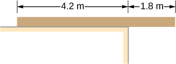
A uniform plank rests on a level surface as shown below. The plank has a mass of 30 kg and is 6.0 m long. How much mass can be placed at its right end before it tips? (Hint: When the board is about to tip over, it makes contact with the surface only along the edge that becomes a momentary axis of rotation.)
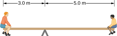
The uniform seesaw shown below is balanced on a fulcrum located 3.0 m from the left end. The smaller boy on the right has a mass of 40 kg and the bigger boy on the left has a mass 80 kg. What is the mass of the board?
40 kg
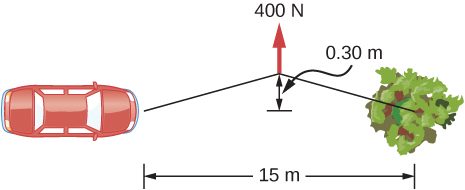
In order to get his car out of the mud, a man ties one end of a rope to the front bumper and the other end to a tree 15 m away, as shown below. He then pulls on the center of the rope with a force of 400 N, which causes its center to be displaced 0.30 m, as shown. What is the force of the rope on the car?
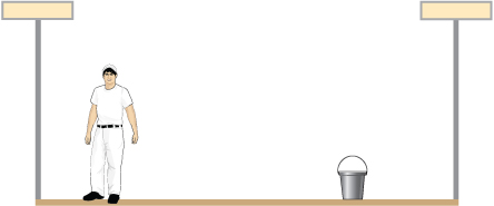
A uniform 40.0-kg scaffold of length 6.0 m is supported by two light cables, as shown below. An 80.0-kg painter stands 1.0 m from the left end of the scaffold, and his painting equipment is 1.5 m from the right end. If the tension in the left cable is twice that in the right cable, find the tensions in the cables and the mass of the equipment.
right cable, 444.3 N; left cable, 888.5 N; weight of equipment 156.8 N; 16.0 kg
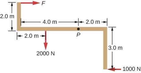
When the structure shown below is supported at point P, it is in equilibrium. Find the magnitude of force F and the force applied at P. The weight of the structure is negligible.
To get up on the roof, a person (mass 70.0 kg) places a 6.00-m aluminum ladder (mass 10.0 kg) against the house on a concrete pad with the base of the ladder 2.00 m from the house. The ladder rests against a plastic rain gutter, which we can assume to be frictionless. The center of mass of the ladder is 2.00 m from the bottom. The person is standing 3.00 m from the bottom. Find the normal reaction and friction forces on the ladder at its base.
784 N, 132.8 N
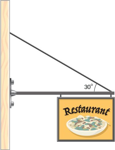
A uniform horizontal strut weighs 400.0 N. One end of the strut is attached to a hinged support at the wall, and the other end of the strut is attached to a sign that weighs 200.0 N. The strut is also supported by a cable attached between the end of the strut and the wall. Assuming that the entire weight of the sign is attached at the very end of the strut, find the tension in the cable and the force at the hinge of the strut.
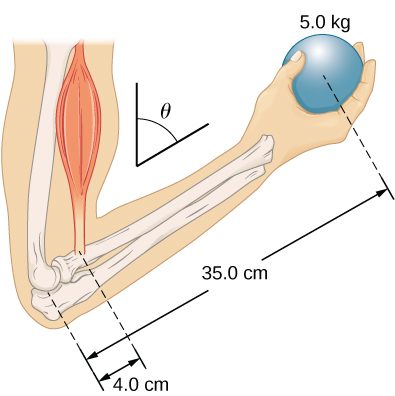
The forearm shown below is positioned at an angle with respect to the upper arm, and a 5.0-kg mass is held in the hand. The total mass of the forearm and hand is 3.0 kg, and their center of mass is 15.0 cm from the elbow. (a) What is the magnitude of the force that the biceps muscle exerts on the forearm for (b) What is the magnitude of the force on the elbow joint for the same angle? (c) How do these forces depend on the angle
a. 539 N; b. 461 N; c. do not depend on the angle
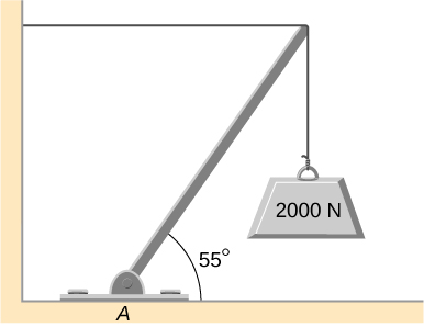
The uniform boom shown below weighs 3000 N. It is supported by the horizontal guy wire and by the hinged support at point A. What are the forces on the boom due to the wire and due to the support at A? Does the force at A act along the boom?
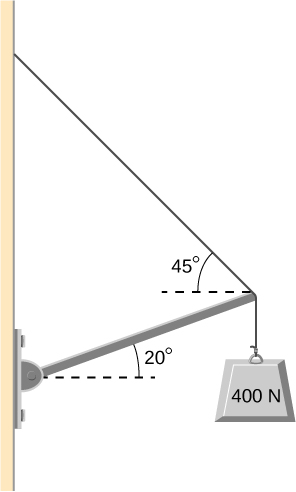
The uniform boom shown below weighs 700 N, and the object hanging from its right end weighs 400 N. The boom is supported by a light cable and by a hinge at the wall. Calculate the tension in the cable and the force on the hinge on the boom. Does the force on the hinge act along the boom?
tension 778 N; at hinge 778 N at above the horizontal; no
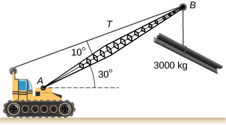
A 12.0-m boom, AB, of a crane lifting a 3000-kg load is shown below. The center of mass of the boom is at its geometric center, and the mass of the boom is 1000 kg. For the position shown, calculate tension T in the cable and the force at the axle A.
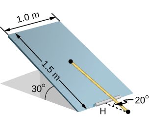
A uniform trapdoor shown below is 1.0 m by 1.5 m and weighs 300 N. It is supported by a single hinge (H), and by a light rope tied between the middle of the door and the floor. The door is held at the position shown, where its slab makes a angle with the horizontal floor and the rope makes a angle with the floor. Find the tension in the rope and the force at the hinge.
1500 N; 1620 N at
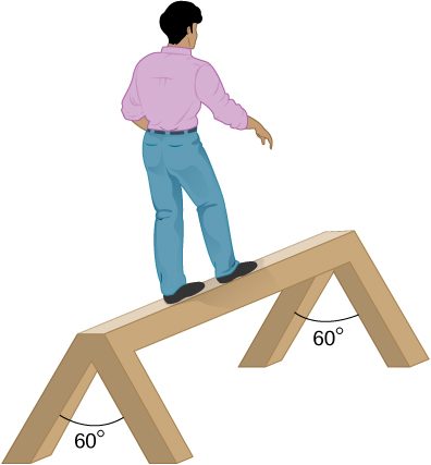
A 90-kg man walks on a sawhorse, as shown below. The sawhorse is 2.0 m long and 1.0 m high, and its mass is 25.0 kg. Calculate the normal reaction force on each leg at the contact point with the floor when the man is 0.5 m from the far end of the sawhorse. (Hint: At each end, find the total reaction force first. This reaction force is the vector sum of two reaction forces, each acting along one leg. The normal reaction force at the contact point with the floor is the normal (with respect to the floor) component of this force.)
Adapted from University Physics Volume 1 by OpenStax (openstax.org), licensed under CC BY-NC-SA 4.0. Changes were made. License: CC-BY-NC-SA-4.0.
These eBooks are a prerelease and are not yet certified conformant with WCAG 2.1 AA or ADA Title II. Every page is built against an automated accessibility gate, and the published editions will meet ADA Title II requirements when they release in late September 2026. If something is unusable, please tell us.