
23.12 RLC Series AC Circuits
Learning Objectives
By the end of this section, you will be able to:
- Calculate the impedance, phase angle, resonant frequency, power, power factor, voltage, and/or current in a RLC series circuit.
- Draw the circuit diagram for an RLC series circuit.
- Explain the significance of the resonant frequency.
Impedance
When alone in an AC circuit, inductors, capacitors, and resistors all impede current. How do they behave when all three occur together? Interestingly, their individual resistances in ohms do not simply add. Because inductors and capacitors behave in opposite ways, they partially to totally cancel each other’s effect. Figure 23.54 shows an RLC series circuit with an AC voltage source, the behavior of which is the subject of this section. The crux of the analysis of an RLC circuit is the frequency dependence of and , and the effect they have on the phase of voltage versus current (established in the preceding section). These give rise to the frequency dependence of the circuit, with important “resonance” features that are the basis of many applications, such as radio tuners.
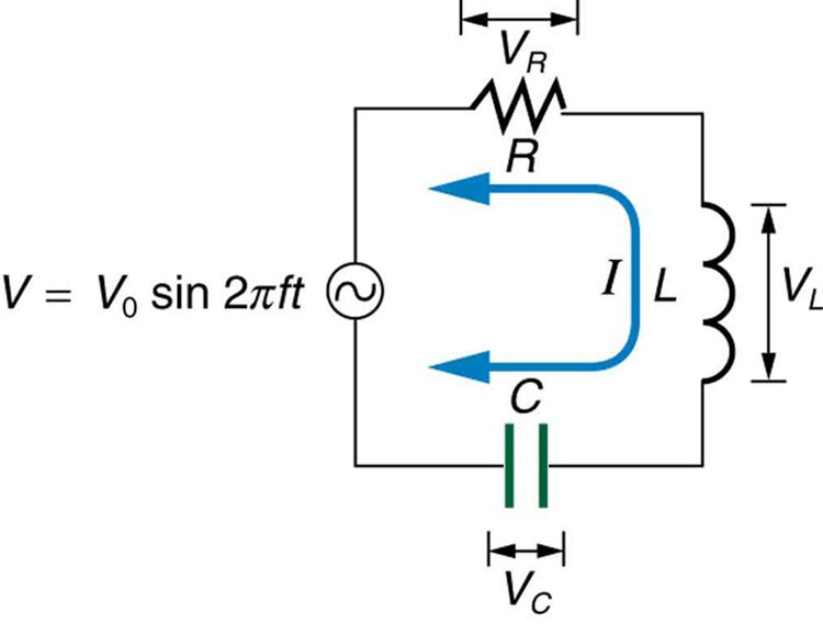
The combined effect of resistance , inductive reactance , and capacitive reactance is defined to be impedance, an AC analogue to resistance in a DC circuit. Current, voltage, and impedance in an RLC circuit are related by an AC version of Ohm’s law:
Here is the peak current, the peak source voltage, and is the impedance of the circuit. The units of impedance are ohms, and its effect on the circuit is as you might expect: the greater the impedance, the smaller the current. To get an expression for in terms of , , and , we will now examine how the voltages across the various components are related to the source voltage. Those voltages are labeled , , and in Figure 23.54.
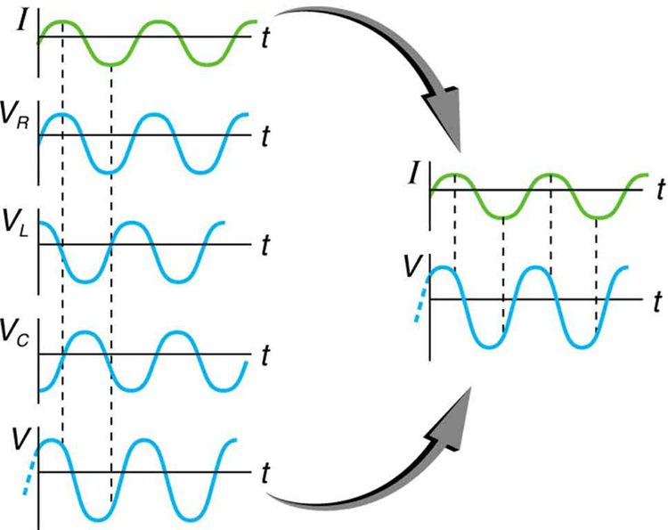
Conservation of charge requires current to be the same in each part of the circuit at all times, so that we can say the currents in , , and are equal and in phase. But we know from the preceding section that the voltage across the inductor leads the current by one-fourth of a cycle, the voltage across the capacitor follows the current by one-fourth of a cycle, and the voltage across the resistor is exactly in phase with the current. Figure 23.55 shows these relationships in one graph, as well as showing the total voltage around the circuit , where all four voltages are the instantaneous values. According to Kirchhoff’s loop rule, the total voltage around the circuit is also the voltage of the source.
You can see from Figure 23.55 that while is in phase with the current, leads by , and follows by . Thus and are out of phase (crest to trough) and tend to cancel, although not completely unless they have the same magnitude. Since the peak voltages are not aligned (not in phase), the peak voltage of the source does not equal the sum of the peak voltages across , , and . The actual relationship is
where , , and are the peak voltages across , , and , respectively. Now, using Ohm’s law and definitions from Reactance, Inductive and Capacitive, we substitute into the above, as well as , , and , yielding
cancels to yield an expression for :
which is the impedance of an RLC series AC circuit. For circuits without a resistor, take ; for those without an inductor, take ; and for those without a capacitor, take .
Resonance in RLC Series AC Circuits
How does an RLC circuit behave as a function of the frequency of the driving voltage source? Combining Ohm’s law, , and the expression for impedance from gives
The reactances vary with frequency, with large at high frequencies and large at low frequencies, as we have seen in three previous examples. At some intermediate frequency , the reactances will be equal and cancel, giving —this is a minimum value for impedance, and a maximum value for results. We can get an expression for by taking
Substituting the definitions of and ,
Solving this expression for yields
where is the resonant frequency of an RLC series circuit. This is also the natural frequency at which the circuit would oscillate if not driven by the voltage source. At , the effects of the inductor and capacitor cancel, so that , and is a maximum.
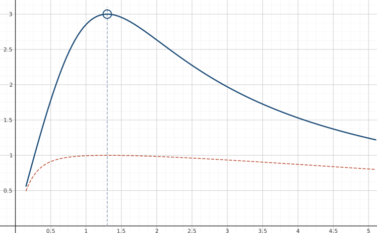
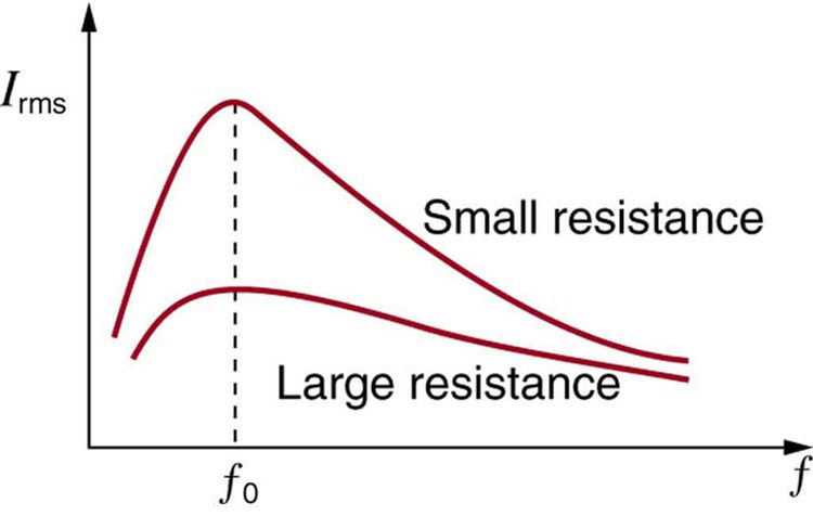
Resonance in AC circuits is analogous to mechanical resonance, where resonance is defined to be a forced oscillation—in this case, forced by the voltage source—at the natural frequency of the system. The receiver in a radio is an RLC circuit that oscillates best at its . A variable capacitor is often used to adjust to receive a desired frequency and to reject others. Figure 23.56 is a graph of current as a function of frequency, illustrating a resonant peak in at . The two curves are for two different circuits, which differ only in the amount of resistance in them. The peak is lower and broader for the higher-resistance circuit. Thus the higher-resistance circuit does not resonate as strongly and would not be as selective in a radio receiver, for example.
Power in RLC Series AC Circuits
If current varies with frequency in an RLC circuit, then the power delivered to it also varies with frequency. But the average power is not simply current times voltage, as it is in purely resistive circuits. As was seen in Figure 23.55, voltage and current are out of phase in an RLC circuit. There is a phase angle between the source voltage and the current , which can be found from
For example, at the resonant frequency or in a purely resistive circuit , so that . This implies that and that voltage and current are in phase, as expected for resistors. At other frequencies, average power is less than at resonance. This is both because voltage and current are out of phase and because is lower. The fact that source voltage and current are out of phase affects the power delivered to the circuit. It can be shown that the average power is
Thus is called the power factor, which can range from 0 to 1. Power factors near 1 are desirable when designing an efficient motor, for example. At the resonant frequency, .
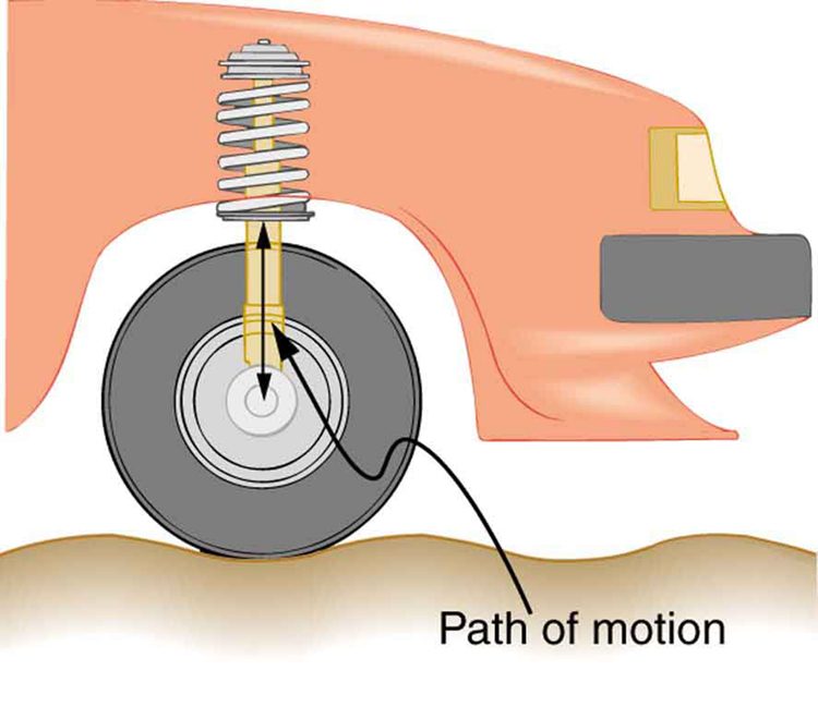
Power delivered to an RLC series AC circuit is dissipated by the resistance alone. The inductor and capacitor have energy input and output but do not dissipate it out of the circuit. Rather they transfer energy back and forth to one another, with the resistor dissipating exactly what the voltage source puts into the circuit. This assumes no significant electromagnetic radiation from the inductor and capacitor, such as radio waves. Such radiation can happen and may even be desired, as we will see in the next chapter on electromagnetic radiation, but it can also be suppressed as is the case in this chapter. The circuit is analogous to the wheel of a car driven over a corrugated road as shown in Figure 23.57. The regularly spaced bumps in the road are analogous to the voltage source, driving the wheel up and down. The shock absorber is analogous to the resistance damping and limiting the amplitude of the oscillation. Energy within the system goes back and forth between kinetic (analogous to maximum current, and energy stored in an inductor) and potential energy stored in the car spring (analogous to no current, and energy stored in the electric field of a capacitor). The amplitude of the wheels’ motion is a maximum if the bumps in the road are hit at the resonant frequency.
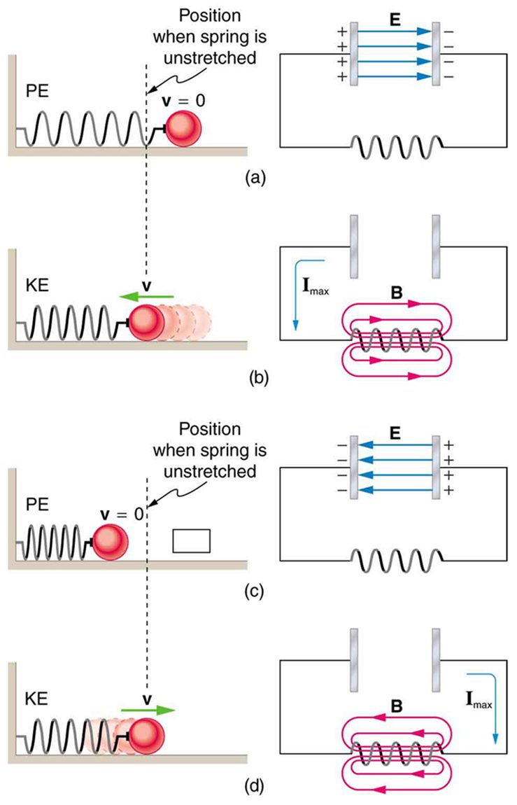
A pure LC circuit with negligible resistance oscillates at , the same resonant frequency as an RLC circuit. It can serve as a frequency standard or clock circuit—for example, in a digital wristwatch. With a very small resistance, only a very small energy input is necessary to maintain the oscillations. The circuit is analogous to a car with no shock absorbers. Once it starts oscillating, it continues at its natural frequency for some time. Figure 23.58 shows the analogy between an LC circuit and a mass on a spring.
Section Summary
- The AC analogy to resistance is impedance , the combined effect of resistors, inductors, and capacitors, defined by the AC version of Ohm’s law: where is the peak current and is the peak source voltage.
- Impedance has units of ohms and is given by .
- The resonant frequency , at which , is
- In an AC circuit, there is a phase angle between source voltage and the current , which can be found from
- for a purely resistive circuit or an RLC circuit at resonance.
- The average power delivered to an RLC circuit is affected by the phase angle and is given by is called the power factor, which ranges from 0 to 1.
Conceptual Questions
Does the resonant frequency of an AC circuit depend on the peak voltage of the AC source? Explain why or why not.
Suppose you have a motor with a power factor significantly less than 1. Explain why it would be better to improve the power factor as a method of improving the motor’s output, rather than to increase the voltage input.
Problems & Exercises
An RL circuit consists of a resistor and a 3.00 mH inductor. (a) Find its impedance at 60.0 Hz and 10.0 kHz. (b) Compare these values of with those found in Example 1 in which there was also a capacitor.
(a) at 60.0 Hz, at 10.0 kHz
(b) At 60 Hz, with a capacitor, , over 13 times as high as without the capacitor. The capacitor makes a large difference at low frequencies. At 10 kHz, with a capacitor , about the same as without the capacitor. The capacitor has a smaller effect at high frequencies.
An RC circuit consists of a resistor and a capacitor. (a) Find its impedance at 60.0 Hz and 10.0 kHz. (b) Compare these values of with those found in Example 1, in which there was also an inductor.
An LC circuit consists of a inductor and a capacitor. (a) Find its impedance at 60.0 Hz and 10.0 kHz. (b) Compare these values of with those found in Example 1 in which there was also a resistor.
(a) at 60.0 Hz, at 10.0 kHz
(b) These values are close to those obtained in Example 1 because at low frequency the capacitor dominates and at high frequency the inductor dominates. So in both cases the resistor makes little contribution to the total impedance.
What is the resonant frequency of a 0.500 mH inductor connected to a capacitor?
To receive AM radio, you want an RLC circuit that can be made to resonate at any frequency between 500 and 1650 kHz. This is accomplished with a fixed inductor connected to a variable capacitor. What range of capacitance is needed?
9.30 nF to 101 nF
Suppose you have a supply of inductors ranging from 1.00 nH to 10.0 H, and capacitors ranging from 1.00 pF to 0.100 F. What is the range of resonant frequencies that can be achieved from combinations of a single inductor and a single capacitor?
What capacitance do you need to produce a resonant frequency of 1.00 GHz, when using an 8.00 nH inductor?
3.17 pF
What inductance do you need to produce a resonant frequency of 60.0 Hz, when using a capacitor?
The lowest frequency in the FM radio band is 88.0 MHz. (a) What inductance is needed to produce this resonant frequency if it is connected to a 2.50 pF capacitor? (b) The capacitor is variable, to allow the resonant frequency to be adjusted to as high as 108 MHz. What must the capacitance be at this frequency?
(a)
(b) 1.66 pF
An RLC series circuit has a resistor, a inductor, and an capacitor.(a) Find the circuit’s impedance at 120 Hz. (b) Find the circuit’s impedance at 5.00 kHz. (c) If the voltage source has , what is at each frequency? (d) What is the resonant frequency of the circuit? (e) What is at resonance?
An RLC series circuit has a resistor, a inductor, and a 25.0 nF capacitor. (a) Find the circuit’s impedance at 500 Hz. (b) Find the circuit’s impedance at 7.50 kHz. (c) If the voltage source has , what is at each frequency? (d) What is the resonant frequency of the circuit? (e) What is at resonance?
(a)
(b)
(c) 31.9 mA at 500 Hz, 312 mA at 7.50 kHz
(d) 82.2 kHz
(e) 0.408 A
An RLC series circuit has a resistor, a inductor, and an capacitor. (a) Find the power factor at . (b) What is the phase angle at 120 Hz? (c) What is the average power at 120 Hz? (d) Find the average power at the circuit’s resonant frequency.
An RLC series circuit has a resistor, a inductor, and a 25.0 nF capacitor. (a) Find the power factor at . (b) What is the phase angle at this frequency? (c) What is the average power at this frequency? (d) Find the average power at the circuit’s resonant frequency.
(a) 0.159
(b)
(c) 26.4 W
(d) 166 W
An RLC series circuit has a resistor and a 25.0 mH inductor. At 8000 Hz, the phase angle is . (a) What is the impedance? (b) Find the circuit’s capacitance. (c) If is applied, what is the average power supplied?
Referring to Example 3, find the average power at 10.0 kHz.
16.0 W
Critical Thinking A length of 4.000 m of wire is to be used to detect a magnetic field. The wire is made into a single square loop and rotated at a rate of 400 cycles per second. (a) If the magnetic field is 0.02000 T, what is the magnitude of the average emf that can be generated in the first quarter cycle, provided the loop is initially oriented in a plane perpendicular to the magnetic field? (b) Is there a difference in the magnitude of the average emf generated if the wire is made into two square loops and rotated at the same rate, starting with the same orientation of the loops as that of the loop in part a? If so, what is the average emf possible for the first quarter cycle for two loops being rotated at 400 cycles per second in the magnetic field? (c) If the wire is made into a figure eight, what is the average emf for the first quarter cycle that can be generated by rotating it at 400 cycles per second in the magnetic field, again starting with the same orientation of the oops with respect to the magnetic field? The wire crosses itself in this arrangement. (d) Does the shape of the loop matter?
(a)
(b)
(c) The average emf is 0 since the loops are made by a wire that crosses, so the voltage from each loop cancels the emf from the other.
(d) No.
Adapted from College Physics 2e by OpenStax (openstax.org), licensed under CC BY-NC-SA 4.0. Changes were made. License: CC-BY-NC-SA-4.0.