
23.11 Reactance, Inductive and Capacitive
Learning Objectives
By the end of this section, you will be able to:
- Sketch voltage and current versus time in simple inductive, capacitive, and resistive circuits.
- Calculate inductive and capacitive reactance.
- Calculate current and/or voltage in simple inductive, capacitive, and resistive circuits.
Many circuits also contain capacitors and inductors, in addition to resistors and an AC voltage source. We have seen how capacitors and inductors respond to DC voltage when it is switched on and off. We will now explore how inductors and capacitors react to sinusoidal AC voltage.
Inductors and Inductive Reactance
Suppose an inductor is connected directly to an AC voltage source, as shown in Figure 23.50. It is reasonable to assume negligible resistance, since in practice we can make the resistance of an inductor so small that it has a negligible effect on the circuit. Also shown is a graph of voltage and current as functions of time.
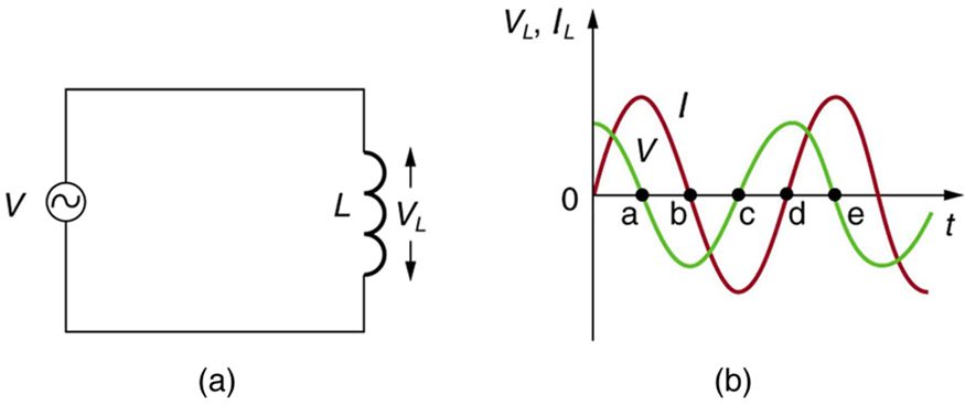
The graph in Figure 23.50(b) starts with voltage at a maximum. Note that the current starts at zero and rises to its peak after the voltage that drives it, just as was the case when DC voltage was switched on in the preceding section. When the voltage becomes negative at point a, the current begins to decrease; it becomes zero at point b, where voltage is its most negative. The current then becomes negative, again following the voltage. The voltage becomes positive at point c and begins to make the current less negative. At point d, the current goes through zero just as the voltage reaches its positive peak to start another cycle. This behavior is summarized as follows:
Current lags behind voltage, since inductors oppose change in current. Changing current induces a back emf . This is considered to be an effective resistance of the inductor to AC. The rms current through an inductor is given by a version of Ohm’s law:
where is the rms voltage across the inductor and is defined to be
with the frequency of the AC voltage source in hertz (An analysis of the circuit using Kirchhoff’s loop rule and calculus actually produces this expression). is called the inductive reactance, because the inductor reacts to impede the current. has units of ohms (, so that frequency times inductance has units of ), consistent with its role as an effective resistance. It makes sense that is proportional to , since the greater the induction the greater its resistance to change. It is also reasonable that is proportional to frequency , since greater frequency means greater change in current. That is, is large for large frequencies (large , small ). The greater the change, the greater the opposition of an inductor.
Note that although the resistance in the circuit considered is negligible, the AC current is not extremely large because inductive reactance impedes its flow. With AC, there is no time for the current to become extremely large.
Capacitors and Capacitive Reactance
Consider the capacitor connected directly to an AC voltage source as shown in Figure 23.51. The resistance of a circuit like this can be made so small that it has a negligible effect compared with the capacitor, and so we can assume negligible resistance. Voltage across the capacitor and current are graphed as functions of time in the figure.
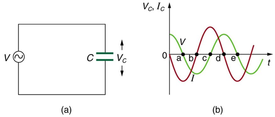
The graph in Figure 23.51 starts with voltage across the capacitor at a maximum. The current is zero at this point, because the capacitor is fully charged and halts the flow. Then voltage drops and the current becomes negative as the capacitor discharges. At point a, the capacitor has fully discharged ( on it) and the voltage across it is zero. The current remains negative between points a and b, causing the voltage on the capacitor to reverse. This is complete at point b, where the current is zero and the voltage has its most negative value. The current becomes positive after point b, neutralizing the charge on the capacitor and bringing the voltage to zero at point c, which allows the current to reach its maximum. Between points c and d, the current drops to zero as the voltage rises to its peak, and the process starts to repeat. Throughout the cycle, the voltage follows what the current is doing by one-fourth of a cycle:
The capacitor is affecting the current, having the ability to stop it altogether when fully charged. Since an AC voltage is applied, there is an rms current, but it is limited by the capacitor. This is considered to be an effective resistance of the capacitor to AC, and so the rms current in the circuit containing only a capacitor is given by another version of Ohm’s law to be
where is the rms voltage and is defined (As with , this expression for results from an analysis of the circuit using Kirchhoff’s rules and calculus) to be
where is called the capacitive reactance, because the capacitor reacts to impede the current. has units of ohms (verification left as an exercise for the reader). is inversely proportional to the capacitance ; the larger the capacitor, the greater the charge it can store and the greater the current that can flow. It is also inversely proportional to the frequency ; the greater the frequency, the less time there is to fully charge the capacitor, and so it impedes current less.
Although a capacitor is basically an open circuit, there is an rms current in a circuit with an AC voltage applied to a capacitor. This is because the voltage is continually reversing, charging and discharging the capacitor. If the frequency goes to zero (DC), tends to infinity, and the current is zero once the capacitor is charged. At very high frequencies, the capacitor’s reactance tends to zero—it has a negligible reactance and does not impede the current (it acts like a simple wire). Capacitors have the opposite effect on AC circuits that inductors have.
Resistors in an AC Circuit
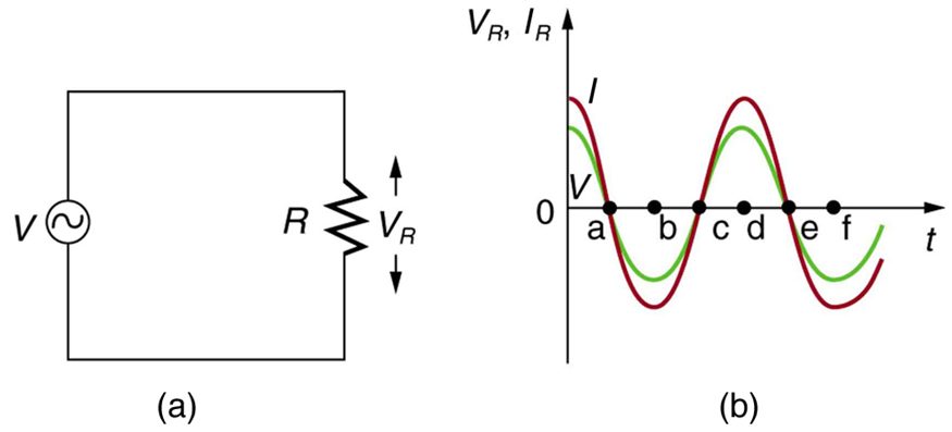
Just as a reminder, consider Figure 23.52, which shows an AC voltage applied to a resistor and a graph of voltage and current versus time. The voltage and current are exactly in phase in a resistor. There is no frequency dependence to the behavior of plain resistance in a circuit:
Section Summary
- For inductors in AC circuits, we find that when a sinusoidal voltage is applied to an inductor, the voltage leads the current by one-fourth of a cycle, or by a phase angle.
- The opposition of an inductor to a change in current is expressed as a type of AC resistance.
- Ohm’s law for an inductor is where is the rms voltage across the inductor.
- is defined to be the inductive reactance, given by with the frequency of the AC voltage source in hertz.
- Inductive reactance has units of ohms and is greatest at high frequencies.
- For capacitors, we find that when a sinusoidal voltage is applied to a capacitor, the voltage follows the current by one-fourth of a cycle, or by a phase angle.
- Since a capacitor can stop current when fully charged, it limits current and offers another form of AC resistance; Ohm’s law for a capacitor is where is the rms voltage across the capacitor.
- is defined to be the capacitive reactance, given by
- has units of ohms and is greatest at low frequencies.
Conceptual Questions
Presbycusis is a hearing loss due to age that progressively affects higher frequencies. A hearing aid amplifier is designed to amplify all frequencies equally. To adjust its output for presbycusis, would you put a capacitor in series or parallel with the hearing aid’s speaker? Explain.
Would you use a large inductance or a large capacitance in series with a system to filter out low frequencies, such as the 100 Hz hum in a sound system? Explain.
High-frequency noise in AC power can damage computers. Does the plug-in unit designed to prevent this damage use a large inductance or a large capacitance (in series with the computer) to filter out such high frequencies? Explain.
Does inductance depend on current, frequency, or both? What about inductive reactance?
Explain why the capacitor in Figure 23.53(a) acts as a low-frequency filter between the two circuits, whereas that in Figure 23.53(b) acts as a high-frequency filter.
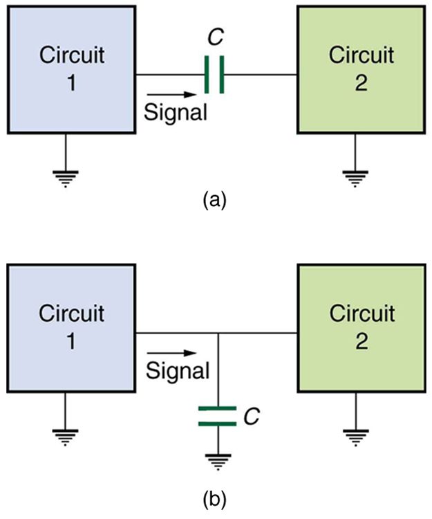
If the capacitors in Figure 23.53 are replaced by inductors, which acts as a low-frequency filter and which as a high-frequency filter?
Problems & Exercises
At what frequency will a 30.0 mH inductor have a reactance of ?
531 Hz
What value of inductance should be used if a reactance is needed at a frequency of 500 Hz?
What capacitance should be used to produce a reactance at 60.0 Hz?
1.33 nF
At what frequency will an 80.0 mF capacitor have a reactance of ?
(a) Find the current through a 0.500 H inductor connected to a 60.0 Hz, 480 V AC source. (b) What would the current be at 100 kHz?
(a) 2.55 A
(b) 1.53 mA
(a) What current flows when a 60.0 Hz, 480 V AC source is connected to a capacitor? (b) What would the current be at 25.0 kHz?
A 20.0 kHz, 16.0 V source connected to an inductor produces a 2.00 A current. What is the inductance?
A 20.0 Hz, 16.0 V source produces a 2.00 mA current when connected to a capacitor. What is the capacitance?
(a) An inductor designed to filter high-frequency noise from power supplied to a personal computer is placed in series with the computer. What minimum inductance should it have to produce a reactance for 15.0 kHz noise? (b) What is its reactance at 60.0 Hz?
(a) 21.2 mH
(b)
The capacitor in Figure 23.53(a) is designed to filter low-frequency signals, impeding their transmission between circuits. (a) What capacitance is needed to produce a reactance at a frequency of 120 Hz? (b) What would its reactance be at 1.00 MHz? (c) Discuss the implications of your answers to (a) and (b).
The capacitor in Figure 23.53(b) will filter high-frequency signals by shorting them to earth/ground. (a) What capacitance is needed to produce a reactance of for a 5.00 kHz signal? (b) What would its reactance be at 3.00 Hz? (c) Discuss the implications of your answers to (a) and (b).
(a) 3.18 mF
(b)
Unreasonable Results
In a recording of voltages due to brain activity (an EEG), a 10.0 mV signal with a 0.500 Hz frequency is applied to a capacitor, producing a current of 100 mA. Resistance is negligible. (a) What is the capacitance? (b) What is unreasonable about this result? (c) Which assumption or premise is responsible?
Construct Your Own Problem
Consider the use of an inductor in series with a computer operating on 60 Hz electricity. Construct a problem in which you calculate the relative reduction in voltage of incoming high frequency noise compared to 60 Hz voltage. Among the things to consider are the acceptable series reactance of the inductor for 60 Hz power and the likely frequencies of noise coming through the power lines.
Adapted from College Physics 2e by OpenStax (openstax.org), licensed under CC BY-NC-SA 4.0. Changes were made. License: CC-BY-NC-SA-4.0.