
21.3 Kirchhoff’s Rules
Learning Objectives
By the end of this section, you will be able to:
- Analyze a complex circuit using Kirchhoff’s rules, using the conventions for determining the correct signs of various terms.
Many complex circuits, such as the one in Figure 21.27, cannot be analyzed with the series-parallel techniques developed in Resistors in Series and Parallel and Electromotive Force: Terminal Voltage. There are, however, two circuit analysis rules that can be used to analyze any circuit, simple or complex. These rules are special cases of the laws of conservation of charge and conservation of energy. The rules are known as Kirchhoff’s rules, after their inventor Gustav Kirchhoff (1824–1887).
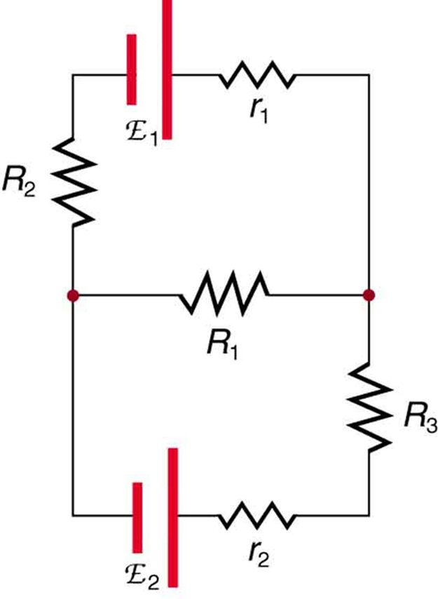
Explanations of the two rules will now be given, followed by problem-solving hints for applying Kirchhoff’s rules, and a worked example that uses them.
Kirchhoff’s First Rule
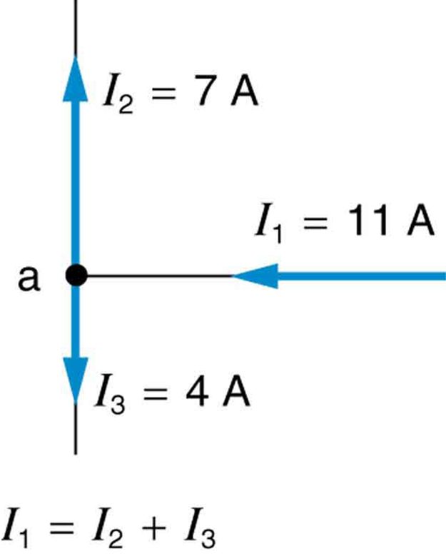
Kirchhoff’s first rule (the junction rule) is an application of the conservation of charge to a junction; it is illustrated in Figure 21.28. Current is the flow of charge, and charge is conserved; thus, whatever charge flows into the junction must flow out. Kirchhoff’s first rule requires that (see figure). Equations like this can and will be used to analyze circuits and to solve circuit problems.
Kirchhoff’s Second Rule
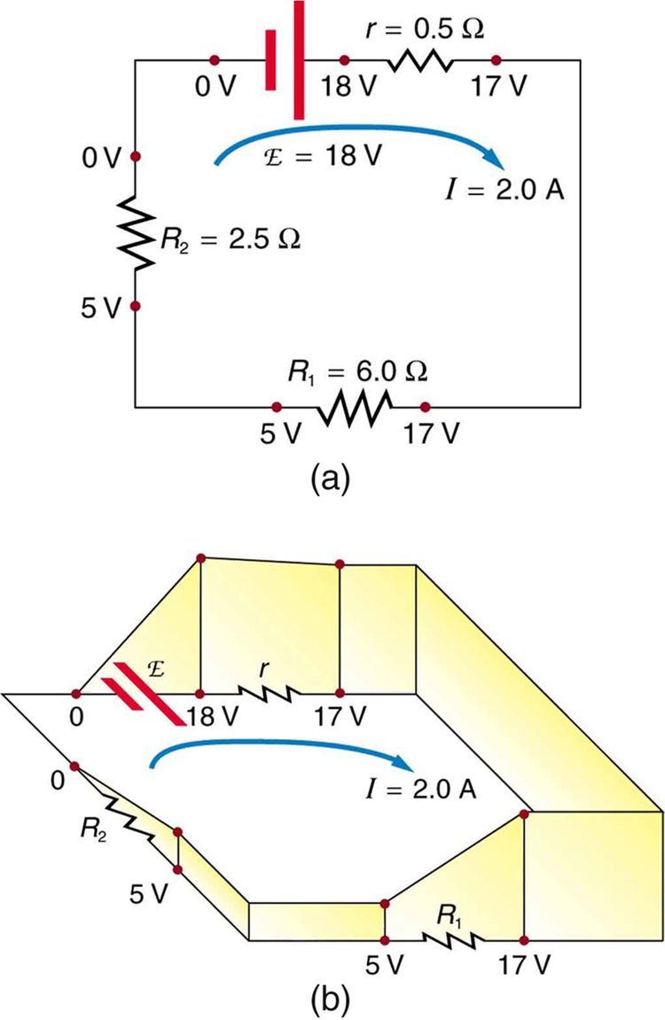
Kirchhoff’s second rule (the loop rule) is an application of conservation of energy. The loop rule is stated in terms of potential, , rather than potential energy, but the two are related since . Recall that emf is the potential difference of a source when no current is flowing. In a closed loop, whatever energy is supplied by emf must be transferred into other forms by devices in the loop, since there are no other ways in which energy can be transferred into or out of the circuit. Figure 21.29 illustrates the changes in potential in a simple series circuit loop.
Kirchhoff’s second rule requires . Rearranged, this is , which means the emf equals the sum of the (voltage) drops in the loop.
Applying Kirchhoff’s Rules
By applying Kirchhoff’s rules, we generate equations that allow us to find the unknowns in circuits. The unknowns may be currents, emfs, or resistances. Each time a rule is applied, an equation is produced. If there are as many independent equations as unknowns, then the problem can be solved. There are two decisions you must make when applying Kirchhoff’s rules. These decisions determine the signs of various quantities in the equations you obtain from applying the rules.
- When applying Kirchhoff’s first rule, the junction rule, you must label the current in each branch and decide in what direction it is going. For example, in Figure 21.27, Figure 21.28, and Figure 21.29, currents are labeled , , , and , and arrows indicate their directions. There is no risk here, for if you choose the wrong direction, the current will be of the correct magnitude but negative.
- When applying Kirchhoff’s second rule, the loop rule, you must identify a closed loop and decide in which direction to go around it, clockwise or counterclockwise. For example, in Figure 21.29 the loop was traversed in the same direction as the current (clockwise). Again, there is no risk; going around the circuit in the opposite direction reverses the sign of every term in the equation, which is like multiplying both sides of the equation by
Figure 21.30 and the following points will help you get the plus or minus signs right when applying the loop rule. Note that the resistors and emfs are traversed by going from a to b. In many circuits, it will be necessary to construct more than one loop. In traversing each loop, one needs to be consistent for the sign of the change in potential. (See Example 1.)
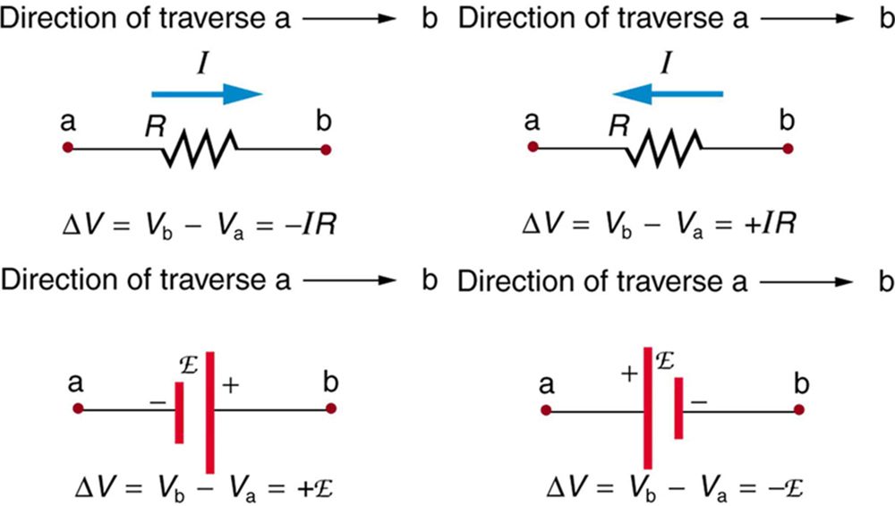
- When a resistor is traversed in the same direction as the current, the change in potential is . (See Figure 21.30.)
- When a resistor is traversed in the direction opposite to the current, the change in potential is . (See Figure 21.30.)
- When an emf is traversed from to + (the same direction it moves positive charge), the change in potential is +emf. (See Figure 21.30.)
- When an emf is traversed from + to (opposite to the direction it moves positive charge), the change in potential is emf. (See Figure 21.30.)
The material in this section is correct in theory. We should be able to verify it by making measurements of current and voltage. In fact, some of the devices used to make such measurements are straightforward applications of the principles covered so far and are explored in the next modules. As we shall see, a very basic, even profound, fact results—making a measurement alters the quantity being measured.
Can Kirchhoff’s rules be applied to simple series and parallel circuits or are they restricted for use in more complicated circuits that are not combinations of series and parallel?
Kirchhoff's rules can be applied to any circuit since they are applications to circuits of two conservation laws. Conservation laws are the most broadly applicable principles in physics. It is usually mathematically simpler to use the rules for series and parallel in simpler circuits so we emphasize Kirchhoff’s rules for use in more complicated situations. But the rules for series and parallel can be derived from Kirchhoff’s rules. Moreover, Kirchhoff’s rules can be expanded to devices other than resistors and emfs, such as capacitors, and are one of the basic analysis devices in circuit analysis.
Test Prep for AP Courses
An experiment was set up with the circuit diagram shown. Assume R1 = 10 Ω, R2 = R3 = 5 Ω, r = 0 Ω and E = 6 V.
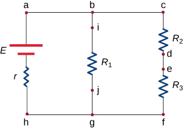
One of the steps to examine the set-up is to test points with the same potential. Which of the following points can be tested?
- Points b, c and d.
- Points d, e and f.
- Points f, h and j.
- Points a, h and i.
At which three points should the currents be measured so that Kirchhoff’s junction rule can be directly confirmed?
- Points b, c and d.
- Points d, e and f.
- Points f, h and j.
- Points a, h and i.
If the current in the branch with the voltage source is upward and currents in the other two branches are downward, i.e. Ia = Ii + Ic, identify which of the following can be true? Select two answers.
- Ii = Ij - If
- Ie = Ih - Ii
- Ic = Ij - Ia
- Id = Ih - Ij
The measurements reveal that the current through R1 is 0.5 A and R3 is 0.6 A. Based on your knowledge of Kirchoff’s laws, confirm which of the following statements are true.
- The measured current for R1 is correct but for R3 is incorrect.
- The measured current for R3 is correct but for R1 is incorrect.
- Both the measured currents are correct.
- Both the measured currents are incorrect.
The graph shown in the following figure is the energy dissipated at R1 as a function of time.
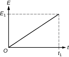
Figure 21.33 Which of the following shows the graph for energy dissipated at R2 as a function of time?
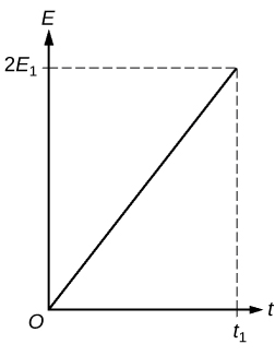
Figure 21.34 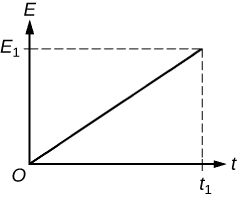
Figure 21.35 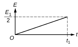
Figure 21.36 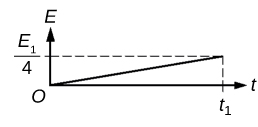
Figure 21.37
For this question, consider the circuit shown in the following figure.
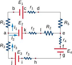
Assuming that none of the three currents (I1, I2, and I3) are equal to zero, which of the following statements is false?
- I3 = I1 + I2 at point a.
- I2 = I3 - I1 at point e.
- The current through R3 is equal to the current through R5.
- The current through R1 is equal to the current through R5.
Which of the following statements is true?
- E1 + E2 + I1R1 - I2R2 + I1r1 - I2r2 + I1R5 = 0
- - E1 + E2 + I1R1 - I2R2 + I1r1 - I2r2 - I1R5 = 0
- E1 - E2 - I1R1 + I2R2 - I1r1 + I2r2 - I1R5 = 0
- E1 + E2 - I1R1 + I2R2 - I1r1 + I2r2 + I1R5 = 0
If I1 = 5 A and I3 = -2 A, which of the following statements is false?
- The current through R1 will flow from a to b and will be equal to 5 A.
- The current through R3 will flow from a to j and will be equal to 2 A.
- The current through R5 will flow from d to e and will be equal to 5 A.
- None of the above.
If I1 = 5 A and I3 = -2 A, I2 will be equal to
- 3 A
- -3 A
- 7 A
- -7 A
a. (c)
b. (c)
c. (d)
d. (d)
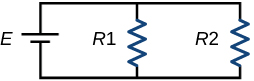
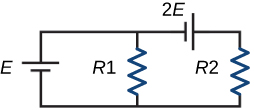
In an experiment this circuit is set up. Three ammeters are used to record the currents in the three vertical branches (with R1, R2, and E). The readings of the ammeters in the resistor branches (i.e. currents in R1 and R2) are 2 A and 3 A respectively.
- Find the equation obtained by applying Kirchhoff’s loop rule in the loop involving R1 and R2.
- What will be the reading of the third ammeter (i.e. the branch with E)? If E were replaced by 3E, how would this reading change?
- If the original circuit is modified by adding another voltage source (as shown in the following circuit), find the readings of the three ammeters.
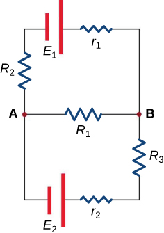
In this circuit, assume the currents through R1, R2 and R3 are I1, I2 and I3 respectively and all are flowing in the clockwise direction.
- Find the equation obtained by applying Kirchhoff’s junction rule at point A.
- Find the equations obtained by applying Kirchhoff’s loop rule in the upper and lower loops.
- Assume R1 = R2 = 6 Ω, R3 = 12 Ω, r1 = r2 = 0 Ω, E1 = 6 V and E2 = 4 V. Calculate I1, I2 and I3.
- For the situation in which E2 is replaced by a closed switch, repeat parts (a) and (b). Using the values for R1, R2, R3, r1 and E1 from part (c) calculate the currents through the three resistors.
- For the circuit in part (d) calculate the output power of the voltage source and across all the resistors. Examine if energy is conserved in the circuit.
- A student implemented the circuit of part (d) in the lab and measured the current though one of the resistors as 0.19 A. According to the results calculated in part (d) identify the resistor(s). Justify any difference in measured and calculated value.
- I1 + I3 = I2
- E1 - I1R1 - I2R2 - I1r1 = 0; - E2 + I1R1 - I3R3 - I3r2 = 0
- I1 = 8/15 A, I2 = 7/15 A and I3 = -1/15 A
- I1 = 2/5 A, I2 = 3/5 A and I3 = 1/5 A
- PE1 = 18/5 W and PR1 = 24/25 W, PR2 = 54/25 W, PR3 = 12/25 W. Yes, PE1 = PR1+ PR2 + PR3
- R3, losses in the circuit
Section Summary
- Kirchhoff’s rules can be used to analyze any circuit, simple or complex.
- Kirchhoff’s first rule—the junction rule: The sum of all currents entering a junction must equal the sum of all currents leaving the junction.
- Kirchhoff’s second rule—the loop rule: The algebraic sum of changes in potential around any closed circuit path (loop) must be zero.
- The two rules are based, respectively, on the laws of conservation of charge and energy.
- When calculating potential and current using Kirchhoff’s rules, a set of conventions must be followed for determining the correct signs of various terms.
- The simpler series and parallel rules are special cases of Kirchhoff’s rules.
Conceptual Questions
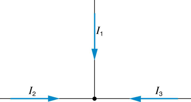
Can all of the currents going into the junction in Figure 21.42 be positive? Explain.
Apply the junction rule to junction b in Figure 21.43. Is any new information gained by applying the junction rule at e? (In the figure, each emf is represented by script E.)
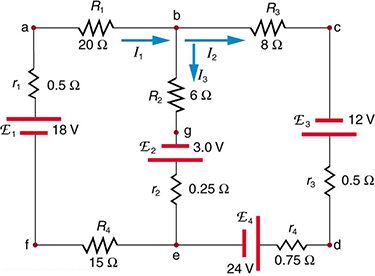
(a) What is the potential difference going from point a to point b in Figure 21.43? (b) What is the potential difference going from c to b? (c) From e to g? (d) From e to d?
Apply the loop rule to loop afedcba in Figure 21.43.
Apply the loop rule to loops abgefa and cbgedc in Figure 21.43.
Problem Exercises
Apply the loop rule to loop abcdefgha in Figure 21.31.
Apply the loop rule to loop aedcba in Figure 21.31.
Verify the second equation in Example 1 by substituting the values found for the currents and .
Verify the third equation in Example 1 by substituting the values found for the currents and .
Apply the junction rule at point a in Figure 21.44.
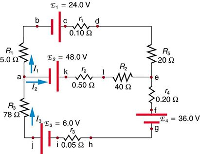
Apply the loop rule to loop abcdefghija in Figure 21.44.
Apply the loop rule to loop akledcba in Figure 21.44.
Find the currents flowing in the circuit in Figure 21.44. Explicitly show how you follow the steps in the Problem-Solving Strategies for Series and Parallel Resistors.
Solve Example 1, but use loop abcdefgha instead of loop akledcba. Explicitly show how you follow the steps in the Problem-Solving Strategies for Series and Parallel Resistors.
(a)
(b)
(c)
Find the currents flowing in the circuit in Figure 21.43.
Unreasonable Results
Consider the circuit in Figure 21.45, and suppose that the emfs are unknown and the currents are given to be , , and . (a) Could you find the emfs? (b) What is wrong with the assumptions?
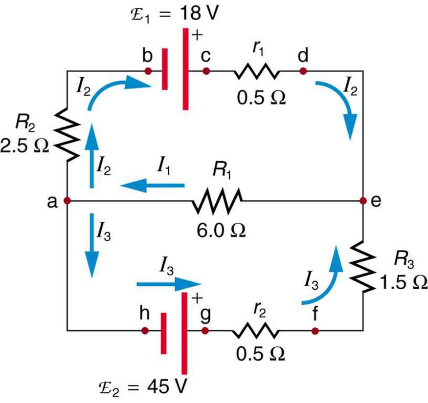
(a) No, you would get inconsistent equations to solve.
(b) . The assumed currents violate the junction rule.
Adapted from College Physics 2e by OpenStax (openstax.org), licensed under CC BY-NC-SA 4.0. Changes were made. License: CC-BY-NC-SA-4.0.