
21.1 Resistors in Series and Parallel
Learning Objectives
By the end of this section, you will be able to:
- Draw a circuit with resistors in parallel and in series.
- Calculate the voltage drop of a current across a resistor using Ohm’s law.
- Contrast the way total resistance is calculated for resistors in series and in parallel.
- Explain why total resistance of a parallel circuit is less than the smallest resistance of any of the resistors in that circuit.
- Calculate total resistance of a circuit that contains a mixture of resistors connected in series and in parallel.
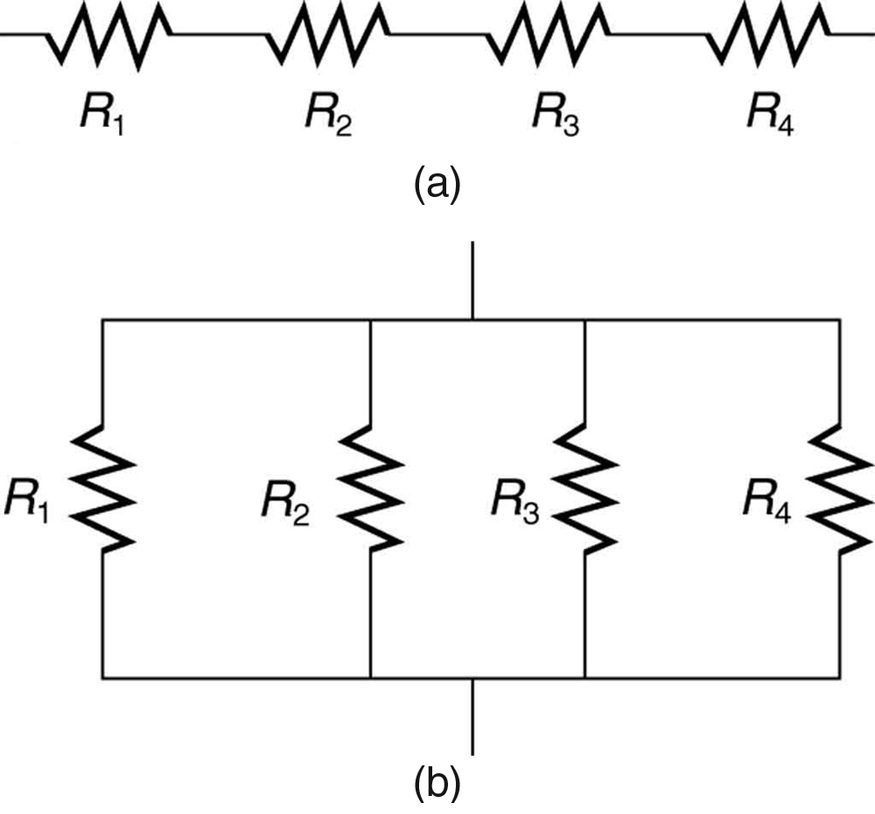
Most circuits have more than one component, called a resistor that limits the flow of charge in the circuit. A measure of this limit on charge flow is called resistance. The simplest combinations of resistors are the series and parallel connections illustrated in Figure 21.2. The total resistance of a combination of resistors depends on both their individual values and how they are connected.
Resistors in Series
When are resistors in series? Resistors are in series whenever the flow of charge, called the current, must flow through devices sequentially. For example, if current flows through a person holding a screwdriver and into the Earth, then in Figure 21.2(a) could be the resistance of the screwdriver’s shaft, the resistance of its handle, the person’s body resistance, and the resistance of her shoes.
Figure 21.3 shows resistors in series connected to a voltage source. It seems reasonable that the total resistance is the sum of the individual resistances, considering that the current has to pass through each resistor in sequence. (This fact would be an advantage to a person wishing to avoid an electrical shock, who could reduce the current by wearing high-resistance rubber-soled shoes. It could be a disadvantage if one of the resistances were a faulty high-resistance cord to an appliance that would reduce the operating current.)
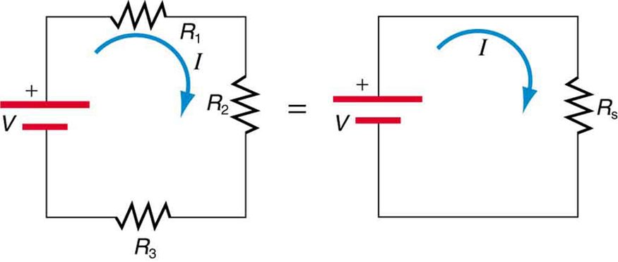
To verify that resistances in series do indeed add, let us consider the loss of electrical power, called a voltage drop, in each resistor in Figure 21.3.
According to Ohm’s law, the voltage drop, , across a resistor when a current flows through it is calculated using the equation , where equals the current in amps (A) and is the resistance in ohms . Another way to think of this is that is the voltage necessary to make a current flow through a resistance .
So the voltage drop across is , that across is , and that across is . The sum of these voltages equals the voltage output of the source; that is,
This equation is based on the conservation of energy and conservation of charge. Electrical potential energy can be described by the equation , where is the electric charge and is the voltage. Thus the energy supplied by the source is , while that dissipated by the resistors is
These energies must be equal, because there is no other source and no other destination for energy in the circuit. Thus, . The charge cancels, yielding , as stated. (Note that the same amount of charge passes through the battery and each resistor in a given amount of time, since there is no capacitance to store charge, there is no place for charge to leak, and charge is conserved.)
Now substituting the values for the individual voltages gives
Note that for the equivalent single series resistance , we have
This implies that the total or equivalent series resistance of three resistors is .
This logic is valid in general for any number of resistors in series; thus, the total resistance of a series connection is
as proposed. Since all of the current must pass through each resistor, it experiences the resistance of each, and resistances in series simply add up.
Resistors in Parallel
Figure 21.4 shows resistors in parallel, wired to a voltage source. Resistors are in parallel when each resistor is connected directly to the voltage source by connecting wires having negligible resistance. Each resistor thus has the full voltage of the source applied to it.
Each resistor draws the same current it would if it alone were connected to the voltage source (provided the voltage source is not overloaded). For example, an automobile’s headlights, radio, and so on, are wired in parallel, so that they utilize the full voltage of the source and can operate completely independently. The same is true in your house, or any building. (See Figure 21.4(b).)
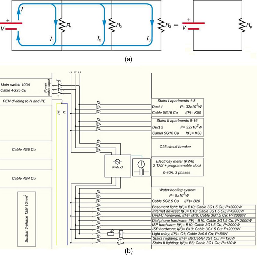
To find an expression for the equivalent parallel resistance , let us consider the currents that flow and how they are related to resistance. Since each resistor in the circuit has the full voltage, the currents flowing through the individual resistors are , , and . Conservation of charge implies that the total current produced by the source is the sum of these currents:
Substituting the expressions for the individual currents gives
Note that Ohm’s law for the equivalent single resistance gives
The terms inside the parentheses in the last two equations must be equal. Generalizing to any number of resistors, the total resistance of a parallel connection is related to the individual resistances by
This relationship results in a total resistance that is less than the smallest of the individual resistances. (This is seen in the next example.) When resistors are connected in parallel, more current flows from the source than would flow for any of them individually, and so the total resistance is lower.
Combinations of Series and Parallel
More complex connections of resistors are sometimes just combinations of series and parallel. These are commonly encountered, especially when wire resistance is considered. In that case, wire resistance is in series with other resistances that are in parallel.
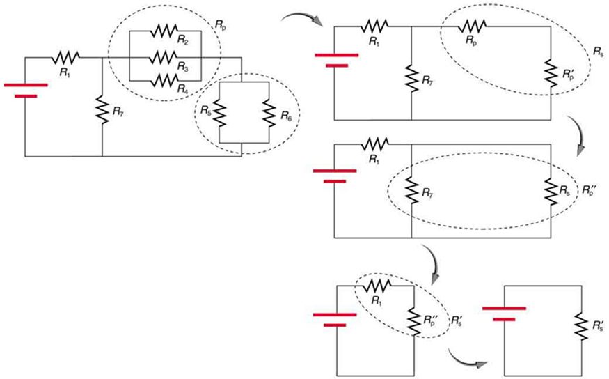
Combinations of series and parallel can be reduced to a single equivalent resistance using the technique illustrated in Figure 21.5. Various parts are identified as either series or parallel, reduced to their equivalents, and further reduced until a single resistance is left. The process is more time consuming than difficult.
The simplest combination of series and parallel resistance, shown in Figure 21.6, is also the most instructive, since it is found in many applications. For example, could be the resistance of wires from a car battery to its electrical devices, which are in parallel. and could be the starter motor and a passenger compartment light. We have previously assumed that wire resistance is negligible, but, when it is not, it has important effects, as the next example indicates.
Practical Implications
One implication of this last example is that resistance in wires reduces the current and power delivered to a resistor. If wire resistance is relatively large, as in a worn (or a very long) extension cord, then this loss can be significant. If a large current is drawn, the drop in the wires can also be significant.
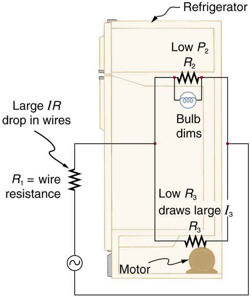
For example, when you are rummaging in the refrigerator and the motor comes on, the refrigerator light dims momentarily. Similarly, you can see the passenger compartment light dim when you start the engine of your car (although this may be due to resistance inside the battery itself).
What is happening in these high-current situations is illustrated in Figure 21.7. The device represented by has a very low resistance, and so when it is switched on, a large current flows. This increased current causes a larger drop in the wires represented by , reducing the voltage across the light bulb (which is ), which then dims noticeably.
Can any arbitrary combination of resistors be broken down into series and parallel combinations? See if you can draw a circuit diagram of resistors that cannot be broken down into combinations of series and parallel.
No, there are many ways to connect resistors that are not combinations of series and parallel, including loops and junctions. In such cases Kirchhoff’s rules, to be introduced in Kirchhoff’s Rules, will allow you to analyze the circuit.
Test Prep for AP Courses
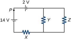
The figure above shows a circuit containing two batteries and three identical resistors with resistance R. Which of the following changes to the circuit will result in an increase in the current at point P? Select two answers.
- Reversing the connections to the 14 V battery.
- Removing the 2 V battery and connecting the wires to close the left loop.
- Rearranging the resistors so all three are in series.
- Removing the branch containing resistor Z.
(a), (b)
In a circuit, a parallel combination of six 1.6-kΩ resistors is connected in series with a parallel combination of four 2.4-kΩ resistors. If the source voltage is 24 V, what will be the percentage of total current in one of the 2.4-kΩ resistors?
- 10%
- 12%
- 20%
- 25%
If the circuit in the previous question is modified by removing some of the 1.6 kΩ resistors, the total current in the circuit is 24 mA. How many resistors were removed?
- 1
- 2
- 3
- 4
(b)
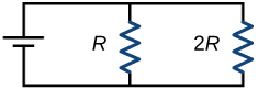
Two resistors, with resistances R and 2R are connected to a voltage source as shown in this figure. If the power dissipated in R is 10 W, what is the power dissipated in 2R?
- 1 W
- 2.5 W
- 5 W
- 10 W
In a circuit, a parallel combination of two 20-Ω and one 10-Ω resistors is connected in series with a 4-Ω resistor. The source voltage is 36 V.
- Find the resistor(s) with the maximum current.
- Find the resistor(s) with the maximum voltage drop.
- Find the power dissipated in each resistor and hence the total power dissipated in all the resistors. Also find the power output of the source. Are they equal or not? Justify your answer.
- Will the answers for questions (a) and (b) differ if a 3 Ω resistor is added in series to the 4 Ω resistor? If yes, repeat the question(s) for the new resistor combination.
- If the values of all the resistors and the source voltage are doubled, what will be the effect on the current?
(a) 4-Ω resistor; (b) combination of 20-Ω, 20-Ω, and 10-Ω resistors; (c) 20 W in each 20-Ω resistor, 40 W in 10-Ω resistor, 64 W in 4-Ω resistor, total 144W total in resistors, output power is 144 W, yes they are equal (law of conservation of energy); (d) 4 Ω and 3 Ω for part (a) and no change for part (b); (e) no effect, it will remain the same.
Section Summary
- The total resistance of an electrical circuit with resistors wired in a series is the sum of the individual resistances:
- Each resistor in a series circuit has the same amount of current flowing through it.
- The voltage drop, or power dissipation, across each individual resistor in a series is different, and their combined total adds up to the power source input.
- The total resistance of an electrical circuit with resistors wired in parallel is less than the lowest resistance of any of the components and can be determined using the formula:
- Each resistor in a parallel circuit has the same full voltage of the source applied to it.
- The current flowing through each resistor in a parallel circuit is different, depending on the resistance.
- If a more complex connection of resistors is a combination of series and parallel, it can be reduced to a single equivalent resistance by identifying its various parts as series or parallel, reducing each to its equivalent, and continuing until a single resistance is eventually reached.
Conceptual Questions
A switch has a variable resistance that is nearly zero when closed and extremely large when open, and it is placed in series with the device it controls. Explain the effect the switch in Figure 21.10 has on current when open and when closed.
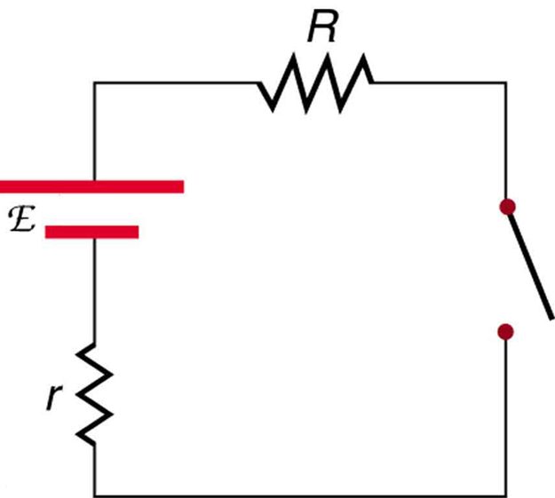
What is the voltage across the open switch in Figure 21.10?
There is a voltage across an open switch, such as in Figure 21.10. Why, then, is the power dissipated by the open switch small?
Why is the power dissipated by a closed switch, such as in Figure 21.10, small?
A student in a physics lab mistakenly wired a light bulb, battery, and switch as shown in Figure 21.11. Explain why the bulb is on when the switch is open, and off when the switch is closed. (Do not try this—it is hard on the battery!)
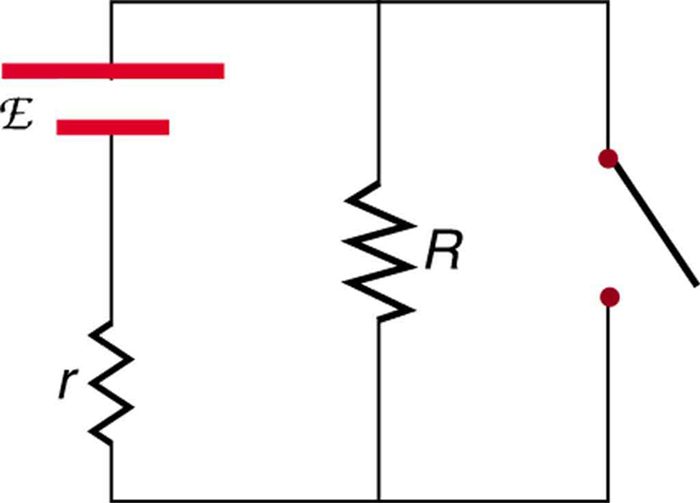
Knowing that the severity of a shock depends on the magnitude of the current through your body, would you prefer to be in series or parallel with a resistance, such as the heating element of a toaster, if shocked by it? Explain.
Would your headlights dim when you start your car’s engine if the wires in your automobile were superconductors? (Do not neglect the battery’s internal resistance.) Explain.
Some strings of holiday lights are wired in series to save wiring costs. An old version utilized bulbs that break the electrical connection, like an open switch, when they burn out. If one such bulb burns out, what happens to the others? If such a string operates on 120 V and has 40 identical bulbs, what is the normal operating voltage of each? Newer versions use bulbs that short circuit, like a closed switch, when they burn out. If one such bulb burns out, what happens to the others? If such a string operates on 120 V and has 39 remaining identical bulbs, what is then the operating voltage of each?
If two household lightbulbs rated 60 W and 100 W are connected in series to household power, which will be brighter? Explain.
Suppose you are doing a physics lab that asks you to put a resistor into a circuit, but all the resistors supplied have a larger resistance than the requested value. How would you connect the available resistances to attempt to get the smaller value asked for?
Before World War II, some radios got power through a “resistance cord” that had a significant resistance. Such a resistance cord reduces the voltage to a desired level for the radio’s tubes and the like, and it saves the expense of a transformer. Explain why resistance cords become warm and waste energy when the radio is on.
Some light bulbs have three power settings (not including zero), obtained from multiple filaments that are individually switched and wired in parallel. What is the minimum number of filaments needed for three power settings?
Problem Exercises
Note: Data taken from figures can be assumed to be accurate to three significant digits.
(a) What is the resistance of ten resistors connected in series? (b) In parallel?
(a)
(b)
(a) What is the resistance of a , a , and a resistor connected in series? (b) In parallel?
What are the largest and smallest resistances you can obtain by connecting a , a , and a resistor together?
(a)
(b)
An 1800-W toaster, a 1400-W electric frying pan, and a 75-W lamp are plugged into the same outlet in a 15-A, 120-V circuit. (The three devices are in parallel when plugged into the same socket.). (a) What current is drawn by each device? (b) Will this combination blow the 15-A fuse?
Your car’s 30.0-W headlight and 2.40-kW starter are ordinarily connected in parallel in a 12.0-V system. What power would one headlight and the starter consume if connected in series to a 12.0-V battery? (Neglect any other resistance in the circuit and any change in resistance in the two devices.)
(a) Given a 48.0-V battery and and resistors, find the current and power for each resistor when connected in series. (b) Repeat when the resistances are in parallel.
Referring to the example combining series and parallel circuits and Figure 21.6, calculate in the following two different ways: (a) from the known values of and ; (b) using Ohm’s law for . In both parts explicitly show how you follow the steps in the Problem-Solving Strategies for Series and Parallel Resistors.
(a) 0.74 A
(b) 0.742 A
Referring to Figure 21.6: (a) Calculate and note how it compares with found in the first two example problems in this module. (b) Find the total power supplied by the source and compare it with the sum of the powers dissipated by the resistors.
Refer to Figure 21.7 and the discussion of lights dimming when a heavy appliance comes on. (a) Given the voltage source is 120 V, the wire resistance is , and the bulb is nominally 75.0 W, what power will the bulb dissipate if a total of 15.0 A passes through the wires when the motor comes on? Assume negligible change in bulb resistance. (b) What power is consumed by the motor?
(a) 67.7 W
(b) 1.64 kW
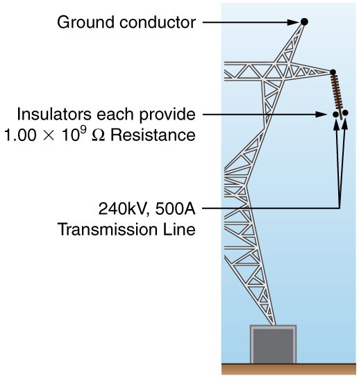
A 240-kV power transmission line carrying is hung from grounded metal towers by ceramic insulators, each having a resistance. Figure 21.12. (a) What is the resistance to ground of 100 of these insulators? (b) Calculate the power dissipated by 100 of them. (c) What fraction of the power carried by the line is this? Explicitly show how you follow the steps in the Problem-Solving Strategies for Series and Parallel Resistors.
Show that if two resistors and are combined and one is much greater than the other (): (a) Their series resistance is very nearly equal to the greater resistance . (b) Their parallel resistance is very nearly equal to smaller resistance .
(a)
(b) ,
so that
Unreasonable Results
Two resistors, one having a resistance of , are connected in parallel to produce a total resistance of . (a) What is the value of the second resistance? (b) What is unreasonable about this result? (c) Which assumptions are unreasonable or inconsistent?
Unreasonable Results
Two resistors, one having a resistance of , are connected in series to produce a total resistance of . (a) What is the value of the second resistance? (b) What is unreasonable about this result? (c) Which assumptions are unreasonable or inconsistent?
(a)
(b) Resistance cannot be negative.
(c) Series resistance is said to be less than one of the resistors, but it must be greater than any of the resistors.
Adapted from College Physics 2e by OpenStax (openstax.org), licensed under CC BY-NC-SA 4.0. Changes were made. License: CC-BY-NC-SA-4.0.