
12.2 Bernoulli’s Equation
Learning Objectives
By the end of this section, you will be able to:
- Explain the terms in Bernoulli’s equation.
- Explain how Bernoulli’s equation is related to conservation of energy.
- Explain how to derive Bernoulli’s principle from Bernoulli’s equation.
- Calculate with Bernoulli’s principle.
- List some applications of Bernoulli’s principle.
When a fluid flows into a narrower channel, its speed increases. That means its kinetic energy also increases. Where does that change in kinetic energy come from? The increased kinetic energy comes from the net work done on the fluid to push it into the channel and the work done on the fluid by the gravitational force, if the fluid changes vertical position. Recall the work-energy theorem,
There is a pressure difference when the channel narrows. This pressure difference results in a net force on the fluid: recall that pressure times area equals force. The net work done increases the fluid’s kinetic energy. As a result, the pressure will drop in a rapidly-moving fluid, whether or not the fluid is confined to a tube.
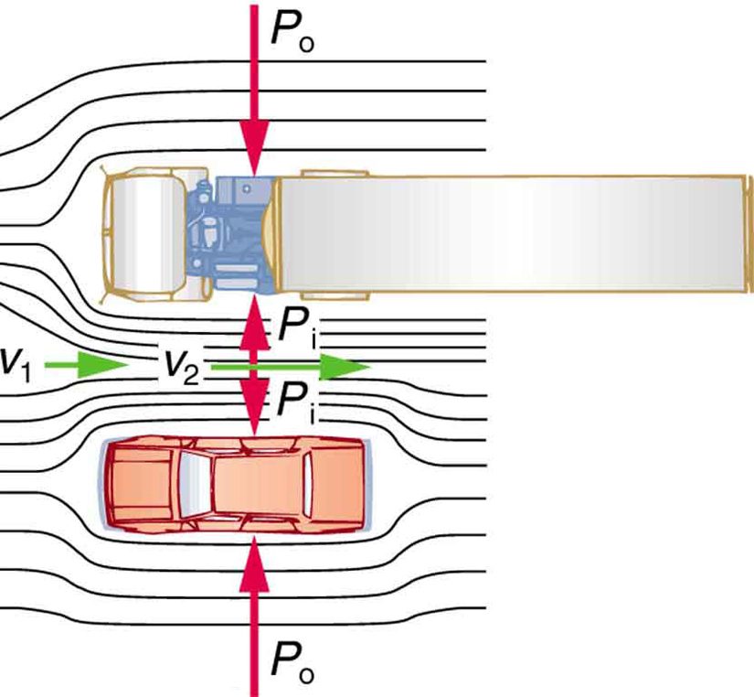
There are a number of common examples of pressure dropping in rapidly-moving fluids. Shower curtains have a disagreeable habit of bulging into the shower stall when the shower is on. The high-velocity stream of water and air creates a region of lower pressure inside the shower, and standard atmospheric pressure on the other side. The pressure difference results in a net force inward pushing the curtain in. You may also have noticed that when passing a truck on the highway, your car tends to veer toward it. The reason is the same—the high velocity of the air between the car and the truck creates a region of lower pressure, and the vehicles are pushed together by greater pressure on the outside. (See Figure 12.5.) This effect was observed as far back as the mid-1800s, when it was found that trains passing in opposite directions tipped precariously toward one another.
Bernoulli’s Equation
The relationship between pressure and velocity in fluids is described quantitatively by Bernoulli’s equation, named after its discoverer, the Swiss scientist Daniel Bernoulli (1700–1782). Bernoulli’s equation states that for an incompressible, frictionless fluid, the following sum is constant:
where is the absolute pressure, is the fluid density, is the velocity of the fluid, is the height above some reference point, and is the acceleration due to gravity. If we follow a small volume of fluid along its path, various quantities in the sum may change, but the total remains constant. Let the subscripts 1 and 2 refer to any two points along the path that the bit of fluid follows; Bernoulli’s equation becomes
Bernoulli’s equation is a form of the conservation of energy principle. Note that the second and third terms are the kinetic and potential energy with replaced by . In fact, each term in the equation has units of energy per unit volume. We can prove this for the second term by substituting into it and gathering terms:
So is the kinetic energy per unit volume. Making the same substitution into the third term in the equation, we find
so is the gravitational potential energy per unit volume. Note that pressure has units of energy per unit volume, too. Since , its units are . If we multiply these by m/m, we obtain , or energy per unit volume. Bernoulli’s equation is, in fact, just a convenient statement of conservation of energy for an incompressible fluid in the absence of friction.
The general form of Bernoulli’s equation has three terms in it, and it is broadly applicable. To understand it better, we will look at a number of specific situations that simplify and illustrate its use and meaning.
Bernoulli’s Equation for Static Fluids
Let us first consider the very simple situation where the fluid is static—that is, . Bernoulli’s equation in that case is
We can further simplify the equation by taking (we can always choose some height to be zero, just as we often have done for other situations involving the gravitational force, and take all other heights to be relative to this). In that case, we get
This equation tells us that, in static fluids, pressure increases with depth. As we go from point 1 to point 2 in the fluid, the depth increases by , and consequently, is greater than by an amount . In the very simplest case, is zero at the top of the fluid, and we get the familiar relationship . (Recall that and ) Bernoulli’s equation includes the fact that the pressure due to the weight of a fluid is . Although we introduce Bernoulli’s equation for fluid flow, it includes much of what we studied for static fluids in the preceding chapter.
Bernoulli’s Principle—Bernoulli’s Equation at Constant Depth
Another important situation is one in which the fluid moves but its depth is constant—that is, . Under that condition, Bernoulli’s equation becomes
Situations in which fluid flows at a constant depth are so important that this equation is often called Bernoulli’s principle. It is Bernoulli’s equation for fluids at constant depth. (Note again that this applies to a small volume of fluid as we follow it along its path.) As we have just discussed, pressure drops as speed increases in a moving fluid. We can see this from Bernoulli’s principle. For example, if is greater than in the equation, then must be less than for the equality to hold.
Applications of Bernoulli’s Principle
There are a number of devices and situations in which fluid flows at a constant height and, thus, can be analyzed with Bernoulli’s principle.
Entrainment
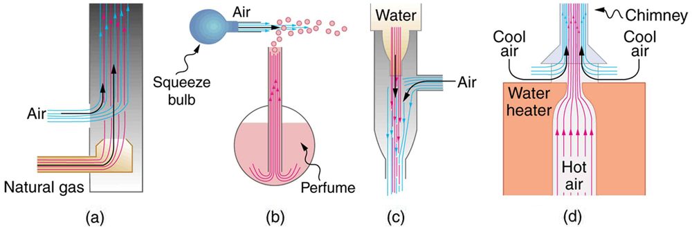
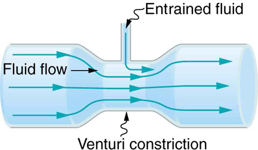
People have long put the Bernoulli principle to work by using reduced pressure in high-velocity fluids to move things about. With a higher pressure on the outside, the high-velocity fluid forces other fluids into the stream. This process is called entrainment. Entrainment devices have been in use since ancient times, particularly as pumps to raise water small heights, as in draining swamps, fields, or other low-lying areas. Some other devices that use the concept of entrainment are shown in Figure 12.6.
Wings and Sails
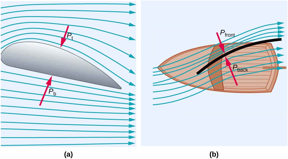
The airplane wing is a beautiful example of Bernoulli’s principle in action. Figure 12.7(a) shows the characteristic shape of a wing. The wing is tilted upward at a small angle and the upper surface is longer, causing air to flow faster over it. The pressure on top of the wing is therefore reduced, creating a net upward force or lift. (Wings can also gain lift by pushing air downward, utilizing the conservation of momentum principle. The deflected air molecules result in an upward force on the wing — Newton’s third law.) Sails also have the characteristic shape of a wing. (See Figure 12.7(b).) The pressure on the front side of the sail, , is lower than the pressure on the back of the sail, . This results in a forward force and even allows you to sail into the wind.
Velocity measurement
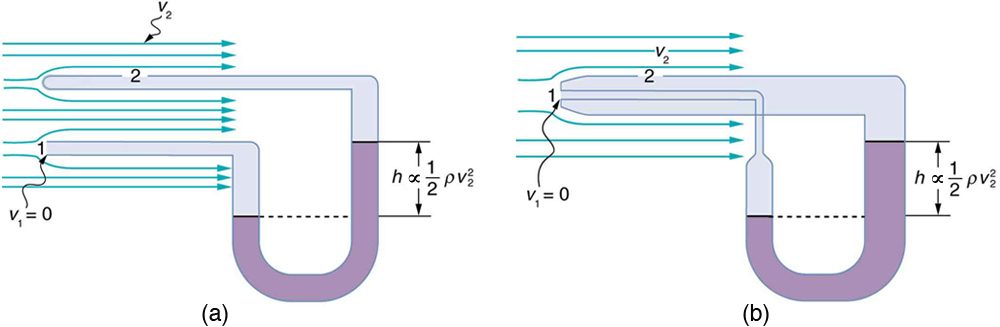
Figure 12.8 shows two devices that measure fluid velocity based on Bernoulli’s principle. The manometer in Figure 12.8(a) is connected to two tubes that are small enough not to appreciably disturb the flow. The tube facing the oncoming fluid creates a dead spot having zero velocity () in front of it, while fluid passing the other tube has velocity . This means that Bernoulli’s principle as stated in becomes
Thus pressure over the second opening is reduced by , and so the fluid in the manometer rises by on the side connected to the second opening, where
(Recall that the symbol means “proportional to.”) Solving for , we see that
Figure 12.8(b) shows a version of this device that is in common use for measuring various fluid velocities; such devices are frequently used as air speed indicators in aircraft.
Test Prep for AP Courses
At what depth beneath the surface of the lake is the pressure in the water equal to twice atmospheric pressure?
- 10 m
- 100 m
- 1000 m
- 10,000 m
(a)
A pump provides pressure to the lower end of a long pipeline that supplies water from a reservoir to a house located on a hill 150 m vertically upward from the lower end of the pipe (where the water is initially at rest before being pumped). The pipeline has a constant diameter of 3.5 cm, and the upper end of the pipeline is open to the atmosphere. What pressure must the pump provide for water to flow from the upper end of the pipeline at a rate of 5.0 m/s?
According to Bernoulli's equation, if the pressure in a given fluid is constant and the kinetic energy per unit volume of a fluid increases, which of the following is true?
- The potential energy per unit volume of the fluid decreases.
- The potential energy per unit volume of the fluid increases.
- The fluid must no longer be considered incompressible.
- The flow rate of the fluid increases.
(a)
Consider the following circumstances within a fluid, and determine the answer using Bernoulli's equation. (a) The pressure and kinetic energy per unit volume along a fluid path increases. What must be true about the potential energy per unit volume of the fluid along the fluid path? Explain. (b) The pressure along a fluid path increases, and the kinetic energy per unit volume remains constant. What must be true about the potential energy per unit volume of the fluid along the fluid path? Explain.
Summary
- Bernoulli’s equation states that the sum on each side of the following equation is constant, or the same at any two points in an incompressible frictionless fluid:
- Bernoulli’s principle is Bernoulli’s equation applied to situations in which depth is constant. The terms involving depth (or height h ) subtract out, yielding
- Bernoulli’s principle has many applications, including entrainment, wings and sails, and velocity measurement.
Conceptual Questions
You can squirt water a considerably greater distance by placing your thumb over the end of a garden hose and then releasing, than by leaving it completely uncovered. Explain how this works.
Water is shot nearly vertically upward in a decorative fountain and the stream is observed to broaden as it rises. Conversely, a stream of water falling straight down from a faucet narrows. Explain why, and discuss whether surface tension enhances or reduces the effect in each case.
Look back to Figure 12.5. Answer the following two questions. Why is less than atmospheric? Why is greater than ?
Give an example of entrainment not mentioned in the text.
Many entrainment devices have a constriction, called a Venturi, such as shown in Figure 12.9. How does this bolster entrainment?
Some chimney pipes have a T-shape, with a crosspiece on top that helps draw up gases whenever there is even a slight breeze. Explain how this works in terms of Bernoulli’s principle.
Is there a limit to the height to which an entrainment device can raise a fluid? Explain your answer.
Why is it preferable for airplanes to take off into the wind rather than with the wind?
Roofs are sometimes pushed off vertically during a tropical cyclone, and buildings sometimes explode outward when hit by a tornado. Use Bernoulli’s principle to explain these phenomena.
Why does a sailboat need a keel?
It is dangerous to stand close to railroad tracks when a rapidly moving commuter train passes. Explain why atmospheric pressure would push you toward the moving train.
What assumptions are made in Bernoulli’s equation? Are these assumptions reasonably valid in the example of water flowing in a hose?
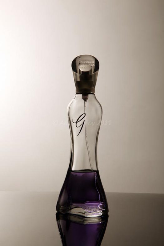
A perfume bottle or atomizer sprays a fluid that is in the bottle. (Figure 12.10.) How does the fluid rise up in the vertical tube in the bottle?
If you lower the window on a car while moving, an empty plastic bag can sometimes fly out the window. Why does this happen?
Problems & Exercises
Verify that pressure has units of energy per unit volume.
Suppose you have a wind speed gauge like the pitot tube shown in Figure 12.8(b). By what factor must wind speed increase to double the value of in the manometer? Is this independent of the moving fluid and the fluid in the manometer?
If the pressure reading of your pitot tube is 15.0 mm Hg at a speed of 200 km/h, what will it be at 700 km/h at the same altitude?
184 mm Hg
Calculate the maximum height to which water could be squirted with the hose in Example 2 in Section 12.1 example if it: (a) Emerges from the nozzle. (b) Emerges with the nozzle removed, assuming the same flow rate.
Every few years, winds in Boulder, Colorado, attain sustained speeds of 45.0 m/s (about 100 mi/h) when the jet stream descends during early spring. Approximately what is the force due to the Bernoulli effect on a roof having an area of ? Typical air density in Boulder is , and the corresponding atmospheric pressure is . (Bernoulli’s principle as stated in the text assumes laminar flow. Using the principle here produces only an approximate result, because there is significant turbulence.)
(a) Calculate the approximate force on a square meter of sail, given the horizontal velocity of the wind is 6.00 m/s parallel to its front surface and 3.50 m/s along its back surface. Take the density of air to be . (The calculation, based on Bernoulli’s principle, is approximate due to the effects of turbulence.) (b) Discuss whether this force is great enough to be effective for propelling a sailboat.
(a) What is the pressure drop due to the Bernoulli effect as water goes into a 3.00-cm-diameter nozzle from a 9.00-cm-diameter fire hose while carrying a flow of 40.0 L/s? (b) To what maximum height above the nozzle can this water rise? (The actual height will be significantly smaller due to air resistance.)
(a)
(b) 163 m
(a) Using Bernoulli’s equation, show that the measured fluid speed for a pitot tube, like the one in Figure 12.8(b), is given by where is the height of the manometer fluid, is the density of the manometer fluid, is the density of the moving fluid, and is the acceleration due to gravity. (Note that is indeed proportional to the square root of , as stated in the text.) (b) Calculate for moving air if a mercury manometer’s is 0.200 m.
Adapted from College Physics 2e by OpenStax (openstax.org), licensed under CC BY-NC-SA 4.0. Changes were made. License: CC-BY-NC-SA-4.0.