
2.8 Microscopes and Telescopes
Microscopes and telescopes are major instruments that have contributed hugely to our current understanding of the micro- and macroscopic worlds. The invention of these devices led to numerous discoveries in disciplines such as physics, astronomy, and biology, to name a few. In this section, we explain the basic physics that make these instruments work.
Microscopes
Although the eye is marvelous in its ability to see objects large and small, it obviously is limited in the smallest details it can detect. The desire to see beyond what is possible with the naked eye led to the use of optical instruments. We have seen that a simple convex lens can create a magnified image, but it is hard to get large magnification with such a lens. A magnification greater than is difficult without distorting the image. To get higher magnification, we can combine the simple magnifying glass with one or more additional lenses. In this section, we examine microscopes that enlarge the details that we cannot see with the naked eye.
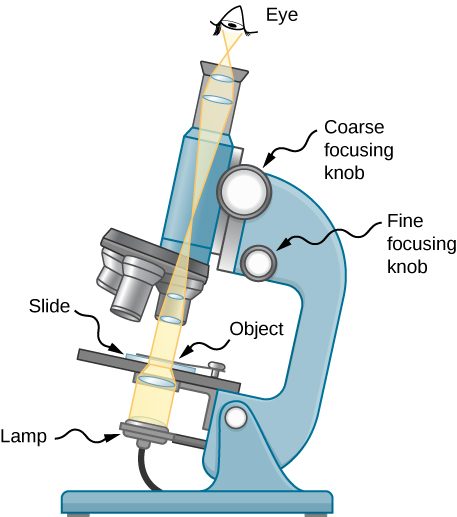
Microscopes were first developed in the early 1600s by eyeglass makers in The Netherlands and Denmark. The simplest compound microscope is constructed from two convex lenses (Figure 2.38). The objective lens is a convex lens of short focal length (i.e., high power) with typical magnification from to . The eyepiece, also referred to as the ocular, is a convex lens of longer focal length.
The purpose of a microscope is to create magnified images of small objects, and both lenses contribute to the final magnification. Also, the final enlarged image is produced sufficiently far from the observer to be easily viewed, since the eye cannot focus on objects or images that are too close (i.e., closer than the near point of the eye).
To see how the microscope in Figure 2.38 forms an image, consider its two lenses in succession. The object is just beyond the focal length of the objective lens, producing a real, inverted image that is larger than the object. This first image serves as the object for the second lens, or eyepiece. The eyepiece is positioned so that the first image is within its focal length , so that it can further magnify the image. In a sense, it acts as a magnifying glass that magnifies the intermediate image produced by the objective. The image produced by the eyepiece is a magnified virtual image. The final image remains inverted but is farther from the observer than the object, making it easy to view.
The eye views the virtual image created by the eyepiece, which serves as the object for the lens in the eye. The virtual image formed by the eyepiece is well outside the focal length of the eye, so the eye forms a real image on the retina.
The magnification of the microscope is the product of the linear magnification by the objective and the angular magnification by the eyepiece. These are given by
Here, and are the focal lengths of the objective and the eyepiece, respectively. We assume that the object and objective focal length are nearly equal and that the final image is formed at the near point of the eye, providing the largest magnification. Note that the angular magnification of the eyepiece is the same as obtained earlier for the simple magnifying glass. This should not be surprising, because the eyepiece is essentially a magnifying glass, and the same physics applies here. The net magnification of the compound microscope is the product of the linear magnification of the objective and the angular magnification of the eyepiece:
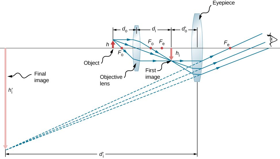
We now calculate the magnifying power of a microscope when the image is at infinity, as shown in Figure 2.39, because this makes for the most relaxed viewing. The magnifying power of the microscope is the product of linear magnification of the objective and the angular magnification of the eyepiece. The magnification of the objective can be obtained from the thin-lens equation for magnification, which is
If the final image is at infinity, then the image created by the objective must be located at the focal point of the eyepiece. This may be seen by considering the thin-lens equation with or by recalling that rays that pass through the focal point exit the lens parallel to each other, which is equivalent to focusing at infinity. For many microscopes, the distance between the image-side focal point of the objective and the object-side focal point of the eyepiece is standardized at . This distance is called the tube length of the microscope. If the length of the compound microscope L is much greater than the focal length of the objective, we can substitute L in for diobj to get
We now need to calculate the angular magnification of the eyepiece with the image at infinity. To do so, we take the ratio of the angle subtended by the image to the angle subtended by the object at the near point of the eye (this is the closest that the unaided eye can view the object, and thus this is the position where the object will form the largest image on the retina of the unaided eye). Using Figure 2.39 and working in the small-angle approximation, we have and , where is the height of the image formed by the objective, which is the object of the eyepiece. Thus, the angular magnification of the eyepiece is
The net magnifying power of the compound microscope with the image at infinity is therefore
The focal distances must be in centimeters. The minus sign indicates that the final image is inverted. Note that the only variables in the equation are the focal distances of the eyepiece and the objective, which makes this equation particularly useful.
Telescopes
Telescopes are meant for viewing distant objects and produce an image that is larger than the image produced in the unaided eye. Telescopes gather far more light than the eye, allowing dim objects to be observed with greater magnification and better resolution. Telescopes were invented around 1600, and Galileo was the first to use them to study the heavens, with monumental consequences. He observed the moons of Jupiter, the craters and mountains on the moon, the details of sunspots, and the fact that the Milky Way is composed of a vast number of individual stars.
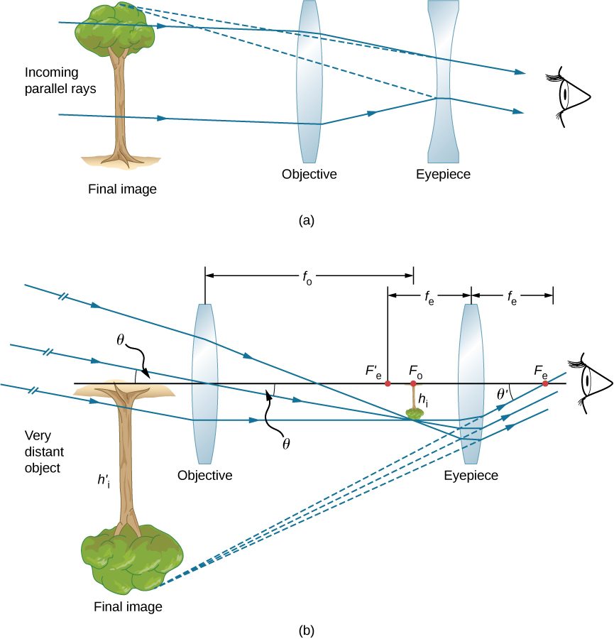
Part (a) of Figure 2.40 shows a refracting telescope made of two lenses. The first lens, called the objective, forms a real image within the focal length of the second lens, which is called the eyepiece. The image of the objective lens serves as the object for the eyepiece, which forms a magnified virtual image that is observed by the eye. This design is what Galileo used to observe the heavens.
Although the arrangement of the lenses in a refracting telescope looks similar to that in a microscope, there are important differences. In a telescope, the real object is far away and the intermediate image is smaller than the object. In a microscope, the real object is very close and the intermediate image is larger than the object. In both the telescope and the microscope, the eyepiece magnifies the intermediate image; in the telescope, however, this is the only magnification.
The most common two-lens telescope is shown in part (b) of the figure. The object is so far from the telescope that it is essentially at infinity compared with the focal lengths of the lenses , so the incoming rays are essentially parallel and focus on the focal plane. Thus, the first image is produced at , as shown in the figure, and is not large compared with what you might see by looking directly at the object. However, the eyepiece of the telescope eyepiece (like the microscope eyepiece) allows you to get nearer than your near point to this first image and so magnifies it (because you are near to it, it subtends a larger angle from your eye and so forms a larger image on your retina). As for a simple magnifier, the angular magnification of a telescope is the ratio of the angle subtended by the image [ in part (b)] to the angle subtended by the real object [ in part (b)]:
To obtain an expression for the magnification that involves only the lens parameters, note that the focal plane of the objective lens lies very close to the focal plane of the eyepiece. If we assume that these planes are superposed, we have the situation shown in Figure 2.41.
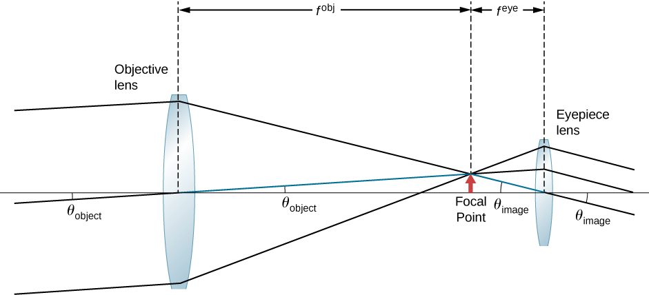
We further assume that the angles and are small, so that the small-angle approximation holds (). If the image formed at the focal plane has height h, then
where the minus sign is introduced because the height is negative if we measure both angles in the counterclockwise direction. Inserting these expressions into Equation 2.39 gives
Thus, to obtain the greatest angular magnification, it is best to have an objective with a long focal length and an eyepiece with a short focal length. The greater the angular magnification M, the larger an object will appear when viewed through a telescope, making more details visible. Limits to observable details are imposed by many factors, including lens quality and atmospheric disturbance. Typical eyepieces have focal lengths of 2.5 cm or 1.25 cm. If the objective of the telescope has a focal length of 1 meter, then these eyepieces result in magnifications of and , respectively. Thus, the angular magnifications make the image appear 40 times or 80 times closer than the real object.
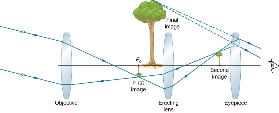
The minus sign in the magnification indicates the image is inverted, which is unimportant for observing the stars but is a real problem for other applications, such as telescopes on ships or telescopic gun sights. If an upright image is needed, Galileo’s arrangement in part (a) of Figure 2.40 can be used. But a more common arrangement is to use a third convex lens as an eyepiece, increasing the distance between the first two and inverting the image once again, as seen in Figure 2.42.
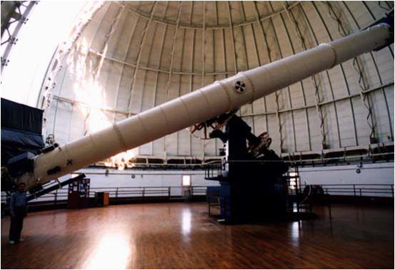
The largest refracting telescope in the world is the 40-inch diameter Yerkes telescope located at Lake Geneva, Wisconsin (Figure 2.43), and operated by the University of Chicago.
It is very difficult and expensive to build large refracting telescopes. You need large defect-free lenses, which in itself is a technically demanding task. A refracting telescope basically looks like a tube with a support structure to rotate it in different directions. A refracting telescope suffers from several problems. The aberration of lenses causes the image to be blurred. Also, as the lenses become thicker for larger lenses, more light is absorbed, making faint stars more difficult to observe. Large lenses are also very heavy and deform under their own weight. Some of these problems with refracting telescopes are addressed by avoiding refraction for collecting light and instead using a curved mirror in its place, as devised by Isaac Newton. These telescopes are called reflecting telescopes.
Reflecting Telescopes
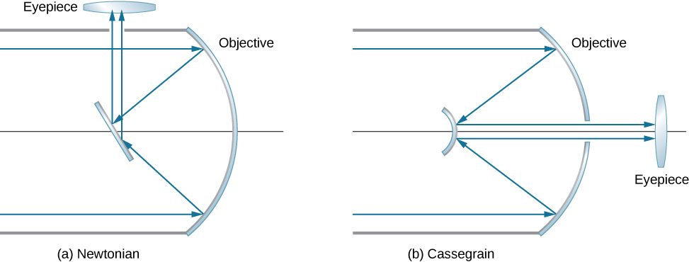
Isaac Newton designed the first reflecting telescope around 1670 to solve the problem of chromatic aberration that happens in all refracting telescopes. In chromatic aberration, light of different colors refracts by slightly different amounts in the lens. As a result, a rainbow appears around the image and the image appears blurred. In the reflecting telescope, light rays from a distant source fall upon the surface of a concave mirror fixed at the bottom end of the tube. The use of a mirror instead of a lens eliminates chromatic aberration. The concave mirror focuses the rays on its focal plane. The design problem is how to observe the focused image. Newton used a design in which the focused light from the concave mirror was reflected to one side of the tube into an eyepiece [part (a) of Figure 2.44]. This arrangement is common in many amateur telescopes and is called the Newtonian design.
Some telescopes reflect the light back toward the middle of the concave mirror using a convex mirror. In this arrangement, the light-gathering concave mirror has a hole in the middle [part (b) of the figure]. The light then is incident on an eyepiece lens. This arrangement of the objective and eyepiece is called the Cassegrain design. Most big telescopes, including the Hubble space telescope, are of this design. Other arrangements are also possible. In some telescopes, a light detector is placed right at the spot where light is focused by the curved mirror.
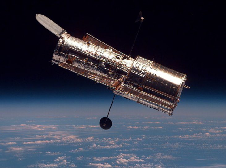
Most astronomical research telescopes are now of the reflecting type. One of the earliest large telescopes of this kind is the Hale 200-inch (or 5-meter) telescope built on Mount Palomar in southern California, which has a 200 inch-diameter mirror. One of the largest telescopes in the world is the 10-meter Keck telescope at the Keck Observatory on the summit of the dormant Mauna Kea volcano in Hawaii. The Keck Observatory operates two 10-meter telescopes. Each is not a single mirror, but is instead made up of 36 hexagonal mirrors. Furthermore, the two telescopes on the Keck can work together, which increases their power to an effective 85-meter mirror. The Hubble telescope (Figure 2.45) is another large reflecting telescope with a 2.4 meter-diameter primary mirror. The Hubble was put into orbit around Earth in 1990.
The angular magnification M of a reflecting telescope is also given by Equation 2.36. Making a large objective mirror helps the telescope collect more light.
Summary
- Many optical devices contain more than a single lens or mirror. These are analyzed by considering each element sequentially. The image formed by the first is the object for the second, and so on. The same ray-tracing and thin-lens techniques developed in the previous sections apply to each lens element.
- The overall magnification of a multiple-element system is the product of the linear magnifications of its individual elements times the angular magnification of the eyepiece. For a two-element system with an objective and an eyepiece, this is where is the linear magnification of the objective and is the angular magnification of the eyepiece.
- The microscope is a multiple-element system that contains more than a single lens or mirror. It allows us to see detail that we could not to see with the unaided eye. Both the eyepiece and objective contribute to the magnification. The magnification of a compound microscope with the image at infinity is In this equation, 16 cm is the standardized distance between the image-side focal point of the objective lens and the object-side focal point of the eyepiece, 25 cm is the normal near point distance, and are the focal distances for the objective lens and the eyepiece, respectively.
- Simple telescopes can be made with two lenses. They are used for viewing objects at large distances.
- The angular magnification M for a telescope is given by where and are the focal lengths of the objective lens and the eyepiece, respectively.
Key Equations
| Image distance in a plane mirror | |
|---|---|
| Focal length for a spherical mirror | |
| Mirror equation | |
| Magnification of a spherical mirror | |
| Sign convention for mirrors | |
| Focal length f | |
| Object distance do | |
| Image distance di | |
| Magnification m | |
| Apparent depth equation | |
| Spherical interface equation | |
| The thin-lens equation | |
| The lens maker’s equation | |
| The magnification m of an object | |
| Optical power | |
| Optical power of thin, closely spaced lenses | |
| Angular magnification M of a simple magnifier | |
| Angular magnification of an object a distance L from the eye for a convex lens of focal length f held a distance ℓ from the eye | |
| Range of angular magnification for a given lens for a person with a near point of 25 cm | |
| Net magnification of compound microscope |
Conceptual Questions
Geometric optics describes the interaction of light with macroscopic objects. Why, then, is it correct to use geometric optics to analyze a microscope’s image?
Microscopes create images of macroscopic size, so geometric optics applies.
The image produced by the microscope in Figure 2.38 cannot be projected. Could extra lenses or mirrors project it? Explain.
If you want your microscope or telescope to project a real image onto a screen, how would you change the placement of the eyepiece relative to the objective?
The eyepiece would be moved slightly farther from the objective so that the image formed by the objective falls just beyond the focal length of the eyepiece.
Problems
A microscope with an overall magnification of 800 has an objective that magnifies by 200. (a) What is the angular magnification of the eyepiece? (b) If there are two other objectives that can be used, having magnifications of 100 and 400, what other total magnifications are possible?
(a) What magnification is produced by a 0.150 cm-focal length microscope objective that is 0.155 cm from the object being viewed? (b) What is the overall magnification if an eyepiece (one that produces an angular magnification of 8.00) is used?
a. ;
b.
Where does an object need to be placed relative to a microscope for its 0.50 cm-focal length objective to produce a linear magnification by the objective of −400?
An amoeba is 0.305 cm away from the 0.300 cm-focal length objective lens of a microscope. (a) Where is the image formed by the objective lens? (b) What is this image’s magnification? (c) An eyepiece with a 2.00-cm focal length is placed 20.0 cm from the objective. Where is the final image? (d) What angular magnification is produced by the eyepiece? (e) What is the overall magnification? (See Figure 2.39.)
a. behind the objective lens;
b. ;
c.
in front of the eyepiece; d. ;
e.
Unreasonable Results Your friends show you an image through a microscope. They tell you that the microscope has an objective with a 0.500-cm focal length and an eyepiece with a 5.00-cm focal length. The resulting overall magnification is 250,000. Are these viable values for a microscope?
Unless otherwise stated, the lens-to-retina distance is 2.00 cm.
What is the angular magnification of a telescope that has a 100 cm-focal length objective and a 2.50 cm-focal length eyepiece?
Find the distance between the objective and eyepiece lenses in the telescope in the above problem needed to produce a final image very far from the observer, where vision is most relaxed. Note that a telescope is normally used to view very distant objects.
A large reflecting telescope has an objective mirror with a 10.0-m radius of curvature. What angular magnification does it produce when a 3.00 m-focal length eyepiece is used?
A small telescope has a concave mirror with a 2.00-m radius of curvature for its objective. Its eyepiece is a 4.00 cm-focal length lens. (a) What is the telescope’s angular magnification? (b) What angle is subtended by a 25,000 km-diameter sunspot? (c) What is the angle of its telescopic image?
A binocular produces an angular magnification of −7.50, acting like a telescope. (Mirrors are used to make the image upright.) If the binoculars have objective lenses with a 75.0-cm focal length, what is the focal length of the eyepiece lenses?
Construct Your Own Problem Consider a telescope of the type used by Galileo, having a convex objective and a concave eyepiece as illustrated in part (a) of Figure 2.40. Construct a problem in which you calculate the location and size of the image produced. Among the things to be considered are the focal lengths of the lenses and their relative placements as well as the size and location of the object. Verify that the angular magnification is greater than one. That is, the angle subtended at the eye by the image is greater than the angle subtended by the object.
Trace rays to find which way the given ray will emerge after refraction through the thin lens in the following figure. Assume thin-lens approximation. (Hint: Pick a point P on the given ray in each case. Treat that point as an object. Now, find its image Q. Use the rule: All rays on the other side of the lens will either go through Q or appear to be coming from Q.)
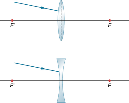
Answers will vary.
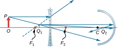
Copy and draw rays to find the final image in the following diagram. (Hint: Find the intermediate image through lens alone. Use the intermediate image as the object for the mirror and work with the mirror alone to find the final image.)
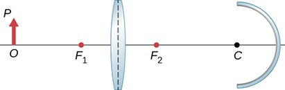
A concave mirror of radius of curvature 10 cm is placed 30 cm from a thin convex lens of focal length 15 cm. Find the location and magnification of a small bulb sitting 50 cm from the lens by using the algebraic method.
12 cm to the left of the mirror,
An object of height 3 cm is placed at 25 cm in front of a converging lens of focal length 20 cm. Behind the lens there is a concave mirror of focal length 20 cm. The distance between the lens and the mirror is 5 cm. Find the location, orientation and size of the final image.
An object of height 3 cm is placed at a distance of 25 cm in front of a converging lens of focal length 20 cm, to be referred to as the first lens. Behind the lens there is another converging lens of focal length 20 cm placed 10 cm from the first lens. There is a concave mirror of focal length 15 cm placed 50 cm from the second lens. Find the location, orientation, and size of the final image.
27 cm in front of the mirror, , orientation upright
An object of height 2 cm is placed at 50 cm in front of a converging lens of focal length 40 cm. Behind the lens, there is a convex mirror of focal length 15 cm placed 30 cm from the converging lens. Find the location, orientation, and size of the final image.
Two concave mirrors are placed facing each other. One of them has a small hole in the middle. A penny is placed on the bottom mirror (see the following figure). When you look from the side, a real image of the penny is observed above the hole. Explain how that could happen.
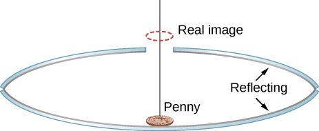
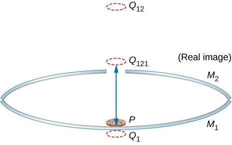
The following figure shows three successive images beginning with the image in mirror . is the image in mirror , whose image in mirror is whose image in mirror is the real image .
A lamp of height 5 cm is placed 40 cm in front of a converging lens of focal length 20 cm. There is a plane mirror 15 cm behind the lens. Where would you find the image when you look in the mirror?
Parallel rays from a faraway source strike a converging lens of focal length 20 cm at an angle of 15 degrees with the horizontal direction. Find the vertical position of the real image observed on a screen in the focal plane.
5.4 cm from the axis
Parallel rays from a faraway source strike a diverging lens of focal length 20 cm at an angle of 10 degrees with the horizontal direction. As you look through the lens, where in the vertical plane the image would appear?
A light bulb is placed 10 cm from a plane mirror, which faces a convex mirror of radius of curvature 8 cm. The plane mirror is located at a distance of 30 cm from the vertex of the convex mirror. Find the location of two images in the convex mirror. Are there other images? If so, where are they located?
Let the vertex of the concave mirror be the origin of the coordinate system. Image 1 is at −10/3 cm (−3.3 cm), image 2 is at −40/11 cm (−3.6 cm). These serve as objects for subsequent images, which are at −310/83 cm (−3.7 cm), −9340/2501 cm (−3.7 cm), −140,720/37,681 cm (−3.7 cm). All remaining images are at approximately −3.7 cm.
A point source of light is 50 cm in front of a converging lens of focal length 30 cm. A concave mirror with a focal length of 20 cm is placed 25 cm behind the lens. Where does the final image form, and what are its orientation and magnification?
Copy and trace to find how a horizontal ray from S comes out after the lens. Use for the prism material.
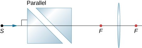
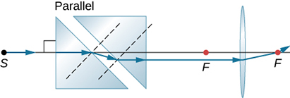
Copy and trace how a horizontal ray from S comes out after the lens. Use for the glass.
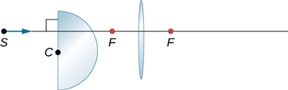
Copy and draw rays to figure out the final image.
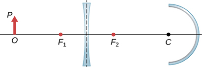
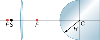
By ray tracing or by calculation, find the place inside the glass where rays from S converge as a result of refraction through the lens and the convex air-glass interface. Use a ruler to estimate the radius of curvature.
A diverging lens has a focal length of 20 cm. What is the power of the lens in diopters?
−5 D
Two lenses of focal lengths of and are glued together with transparent material of negligible thickness. Show that the total power of the two lenses simply add.
What will be the angular magnification of a convex lens with the focal length 2.5 cm?
11
What will be the formula for the angular magnification of a convex lens of focal length f if the eye is very close to the lens and the near point is located a distance D from the eye?
Additional Problems
Use a ruler and a protractor to draw rays to find images in the following cases.
(a) A point object located on the axis of a concave mirror located at a point within the focal length from the vertex.
(b) A point object located on the axis of a concave mirror located at a point farther than the focal length from the vertex.
(c) A point object located on the axis of a convex mirror located at a point within the focal length from the vertex.
(d) A point object located on the axis of a convex mirror located at a point farther than the focal length from the vertex.
(e) Repeat (a)–(d) for a point object off the axis.
a.
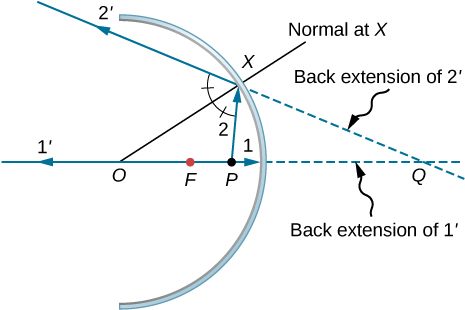
b.
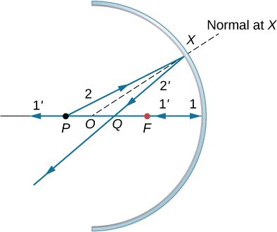
c.
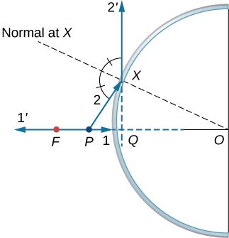
d. similar to the previous picture but with point P outside the focal length; e. Repeat (a)–(d) for a point object off the axis. For a point object placed off axis in front of a concave mirror corresponding to parts (a) and (b), the case for convex mirror left as exercises.
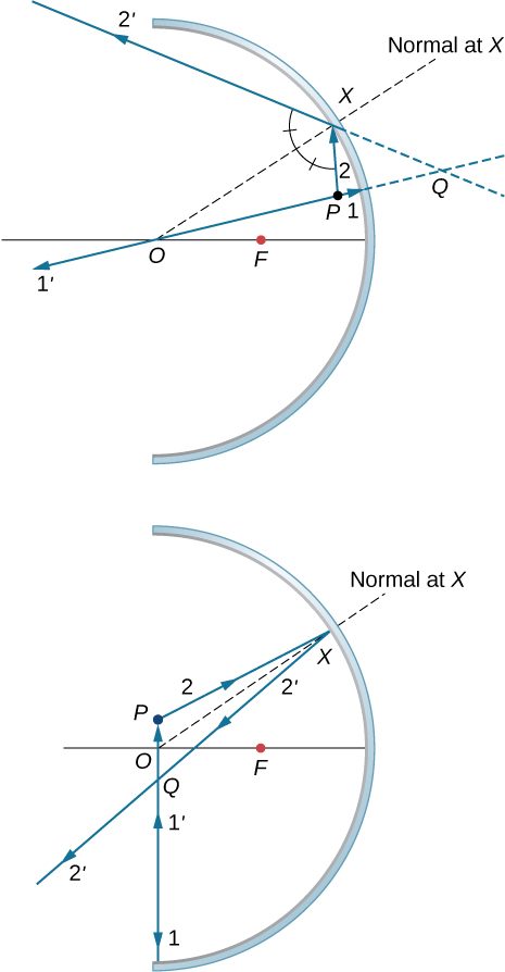
Where should a 3 cm tall object be placed in front of a concave mirror of radius 20 cm so that its image is real and 2 cm tall?
A 3 cm tall object is placed 5 cm in front of a convex mirror of radius of curvature 20 cm. Where is the image formed? How tall is the image? What is the orientation of the image?
, upright
You are looking for a mirror so that you can see a four-fold magnified virtual image of an object when the object is placed 5 cm from the vertex of the mirror. What kind of mirror you will need? What should be the radius of curvature of the mirror?
Derive the following equation for a convex mirror:
,
where VO is the distance to the object O from vertex V, VI the distance to the image I from V, and VF is the distance to the focal point F from V. (Hint: use two sets of similar triangles.)
proof
(a) Draw rays to form the image of a vertical object on the optical axis and farther than the focal point from a converging lens. (b) Use plane geometry in your figure and prove that the magnification m is given by
Use another ray-tracing diagram for the same situation as given in the previous problem to derive the thin-lens equation, .
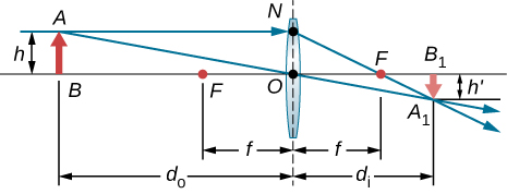
Triangles BAO and are similar triangles. Thus, .Triangles NOF and are similar triangles. Thus, . Noting that gives or . Inverting this gives Equating the two expressions for the ratio gives . Dividing through by gives or .
You photograph a 2.0-m-tall person with a camera that has a 5.0 cm-focal length lens. The image on the film must be no more than 2.0 cm high. (a) What is the closest distance the person can stand to the lens? (b) For this distance, what should be the distance from the lens to the film?
Find the focal length of a thin plano-convex lens. The front surface of this lens is flat, and the rear surface has a radius of curvature of . Assume that the index of refraction of the lens is 1.5.
70 cm
Find the focal length of a meniscus lens with and . Assume that the index of refraction of the lens is 1.5.
A nearsighted man cannot see objects clearly beyond 20 cm from his eyes. How close must he stand to a mirror in order to see what he is doing when he shaves?
The plane mirror has an infinite focal point, so that . The total apparent distance of the man in the mirror will be his actual distance, plus the apparent image distance, or . If this distance must be less than 20 cm, he should stand at .
A mother sees that her child’s contact lens prescription is 0.750 D. What is the child’s near point?
Repeat the previous problem for glasses that are 2.20 cm from the eyes.
Here we want . If near point, . Thus, . Using gives , so the near point is 29.7 cm.
The contact-lens prescription for a nearsighted person is −4.00 D and the person has a far point of 22.5 cm. What is the power of the tear layer between the cornea and the lens if the correction is ideal, taking the tear layer into account?
Unreasonable Results A boy has a near point of 50 cm and a far point of 500 cm. Will a −4.00 D lens correct his far point to infinity?
Assuming a lens at 2.00 cm from the boy’s eye, the image distance must be For an infinite-distance object, the required power is . Therefore, the lens will correct the nearsightedness.
Find the angular magnification of an image by a magnifying glass of if the object is placed from the lens and the lens is close to the eye.
Let objective and eyepiece of a compound microscope have focal lengths of 2.5 cm and 10 cm, respectively and be separated by 12 cm. A object is placed 6.0 cm from the objective. How large is the virtual image formed by the objective-eyepiece system?
Draw rays to scale to locate the image at the retina if the eye lens has a focal length 2.5 cm and the near point is 24 cm. (Hint: Place an object at the near point.)
The objective and the eyepiece of a microscope have the focal lengths 3 cm and 10 cm respectively. Decide about the distance between the objective and the eyepiece if we need a magnification from the objective/eyepiece compound system.
Use, . The image distance for the objective is . Using gives . We want this image to be at the focal point of the eyepiece so that the eyepiece forms an image at infinity for comfortable viewing. Thus, the distance d between the lenses should be .
A far-sighted person has a near point of 100 cm. How far in front or behind the retina does the image of an object placed 25 cm from the eye form? Use the cornea to retina distance of 2.5 cm.
A near-sighted person has afar point of 80 cm. (a) What kind of corrective lens will the person need assuming the distance to the contact lens from the eye is zero? (b) What would be the power of the contact lens needed?
a. focal length of the corrective lens ; b. −1.25 D
In a reflecting telescope the objective is a concave mirror of radius of curvature 2 m and an eyepiece is a convex lens of focal length 5 cm. Find the apparent size of a 25-m tree at a distance of 10 km that you would perceive when looking through the telescope.
Two stars that are apart are viewed by a telescope and found to be separated by an angle of . If the eyepiece of the telescope has a focal length of 1.5 cm and the objective has a focal length of 3 meters, how far away are the stars from the observer?
What is the angular size of the Moon if viewed from a binocular that has a focal length of 1.2 cm for the eyepiece and a focal length of 8 cm for the objective? Use the radius of the moon and the distance of the moon from the observer to be .
An unknown planet at a distance of from Earth is observed by a telescope that has a focal length of the eyepiece of 1 cm and a focal length of the objective of 1 m. If the far away planet is seen to subtend an angle of at the eyepiece, what is the size of the planet?
Adapted from University Physics Volume 3 by OpenStax (openstax.org), licensed under CC BY-NC-SA 4.0. Changes were made. License: CC-BY-NC-SA-4.0.