
8.2 Capacitors in Series and in Parallel
Several capacitors can be connected together to be used in a variety of applications. Multiple connections of capacitors behave as a single equivalent capacitor. The total capacitance of this equivalent single capacitor depends both on the individual capacitors and how they are connected. Capacitors can be arranged in two simple and common types of connections, known as series and parallel, for which we can easily calculate the total capacitance. These two basic combinations, series and parallel, can also be used as part of more complex connections.
The Series Combination of Capacitors
Figure 8.11 illustrates a series combination of three capacitors, arranged in a row within the circuit. As for any capacitor, the capacitance of the combination is related to the charge and voltage by using Equation 8.1. When this series combination is connected to a battery with voltage V, each of the capacitors acquires an identical charge Q. To explain, first note that the charge on the plate connected to the positive terminal of the battery is and the charge on the plate connected to the negative terminal is . Charges are then induced on the other plates so that the sum of the charges on all plates, and the sum of charges on any pair of capacitor plates, is zero. However, the potential drop on one capacitor may be different from the potential drop on another capacitor, because, generally, the capacitors may have different capacitances. The series combination of two or three capacitors resembles a single capacitor with a smaller capacitance. Generally, any number of capacitors connected in series is equivalent to one capacitor whose capacitance (called the equivalent capacitance) is smaller than the smallest of the capacitances in the series combination. Charge on this equivalent capacitor is the same as the charge on any capacitor in a series combination: That is, all capacitors of a series combination have the same charge. This occurs due to the conservation of charge in the circuit. When a charge Q in a series circuit is removed from a plate of the first capacitor (which we denote as ), it must be placed on a plate of the second capacitor (which we denote as and so on.
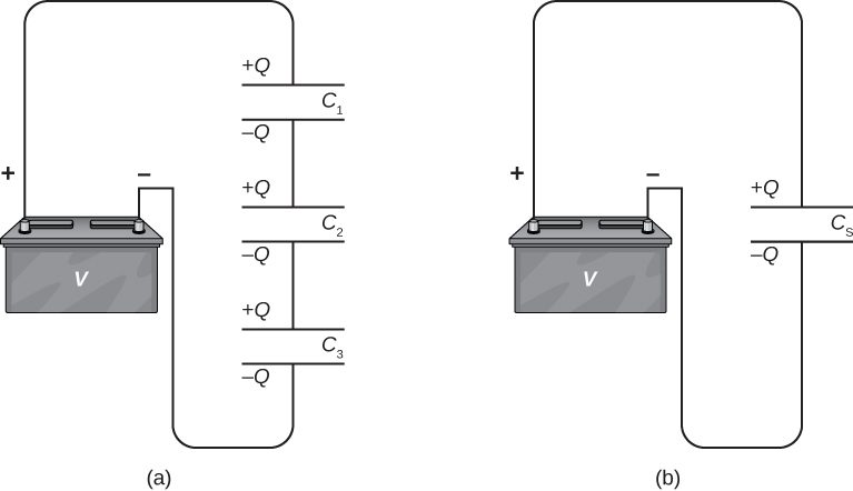
We can find an expression for the total (equivalent) capacitance by considering the voltages across the individual capacitors. The potentials across capacitors 1, 2, and 3 are, respectively, , , and . These potentials must sum up to the voltage of the battery, giving the following potential balance:
Potential V is measured across an equivalent capacitor that holds charge Q and has an equivalent capacitance . Entering the expressions for , , and , we get
Canceling the charge Q, we obtain an expression containing the equivalent capacitance, , of three capacitors connected in series:
This expression can be generalized to any number of capacitors in a series network.
The Parallel Combination of Capacitors
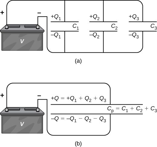
A parallel combination of three capacitors, with one plate of each capacitor connected to one side of the circuit and the other plate connected to the other side, is illustrated in Figure 8.12(a). Since the capacitors are connected in parallel, they all have the same voltage V across their plates. However, each capacitor in the parallel network may store a different charge. To find the equivalent capacitance of the parallel network, we note that the total charge Q stored by the network is the sum of all the individual charges:
On the left-hand side of this equation, we use the relation , which holds for the entire network. On the right-hand side of the equation, we use the relations and for the three capacitors in the network. In this way we obtain
This equation, when simplified, is the expression for the equivalent capacitance of the parallel network of three capacitors:
This expression is easily generalized to any number of capacitors connected in parallel in the network.
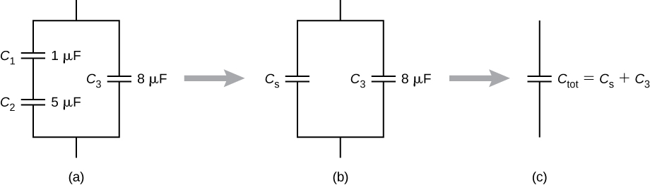
Capacitor networks are usually some combination of series and parallel connections, as shown in Figure 8.13. To find the net capacitance of such combinations, we identify parts that contain only series or only parallel connections, and find their equivalent capacitances. We repeat this process until we can determine the equivalent capacitance of the entire network. The following example illustrates this process.
Summary
- When several capacitors are connected in a series combination, the reciprocal of the equivalent capacitance is the sum of the reciprocals of the individual capacitances.
- When several capacitors are connected in a parallel combination, the equivalent capacitance is the sum of the individual capacitances.
- When a network of capacitors contains a combination of series and parallel connections, we identify the series and parallel networks, and compute their equivalent capacitances step by step until the entire network becomes reduced to one equivalent capacitance.
Conceptual Questions
If you wish to store a large amount of charge in a capacitor bank, would you connect capacitors in series or in parallel? Explain.
What is the maximum capacitance you can get by connecting three capacitors? What is the minimum capacitance?
Problems
A 4.00-pF is connected in series with an 8.00-pF capacitor and a 400-V potential difference is applied across the pair. (a) What is the charge on each capacitor? (b) What is the voltage across each capacitor?
a. 1.07 nC; b. 267 V, 133 V
Three capacitors, with capacitances of , and respectively, are connected in parallel. A 500-V potential difference is applied across the combination. Determine the voltage across each capacitor and the charge on each capacitor.
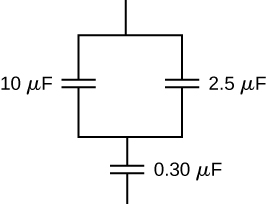
Find the total capacitance of this combination of series and parallel capacitors shown below.
Suppose you need a capacitor bank with a total capacitance of 0.750 F but you have only 1.50-mF capacitors at your disposal. What is the smallest number of capacitors you could connect together to achieve your goal, and how would you connect them?
500 capacitors; connected in parallel
What total capacitances can you make by connecting a and a capacitor?
(series) and (parallel)
Find the equivalent capacitance of the combination of series and parallel capacitors shown below.
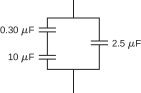
Find the net capacitance of the combination of series and parallel capacitors shown below.
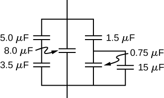
A 40-pF capacitor is charged to a potential difference of 500 V. Its terminals are then connected to those of an uncharged 10-pF capacitor. Calculate: (a) the original charge on the 40-pF capacitor; (b) the charge on each capacitor after the connection is made; and (c) the potential difference across the plates of each capacitor after the connection.
A capacitor and a capacitor are connected in series across a 1.0-kV potential. The charged capacitors are then disconnected from the source and connected to each other with terminals of like sign together. Find the charge on each capacitor and the voltage across each capacitor.
0.89 mC; 1.78 mC; 444 V
Adapted from University Physics Volume 2 by OpenStax (openstax.org), licensed under CC BY-NC-SA 4.0. Changes were made. License: CC-BY-NC-SA-4.0.