
26.4 Microscopes
Learning Objectives
By the end of this section, you will be able to:
- Investigate different types of microscopes.
- Learn how image is formed in a compound microscope.
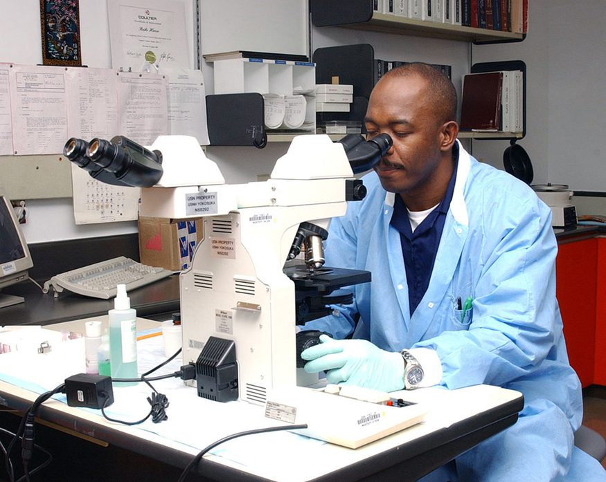
Although the eye is marvelous in its ability to see objects large and small, it obviously has limitations to the smallest details it can detect. Human desire to see beyond what is possible with the naked eye led to the use of optical instruments. In this section we will examine microscopes, instruments for enlarging the detail that we cannot see with the unaided eye. The microscope is a multiple-element system having more than a single lens or mirror. (See Figure 26.15) A microscope can be made from two convex lenses. The image formed by the first element becomes the object for the second element. The second element forms its own image, which is the object for the third element, and so on. Ray tracing helps to visualize the image formed. If the device is composed of thin lenses and mirrors that obey the thin lens equations, then it is not difficult to describe their behavior numerically.
Microscopes were first developed in the early 1600s by eyeglass makers in The Netherlands and Denmark. The simplest compound microscope is constructed from two convex lenses as shown schematically in Figure 26.16. The first lens is called the objective lens, and has typical magnification values from to . In standard microscopes, the objectives are mounted such that when you switch between objectives, the sample remains in focus. Objectives arranged in this way are described as parfocal. The second, the eyepiece, also referred to as the ocular, has several lenses which slide inside a cylindrical barrel. The focusing ability is provided by the movement of both the objective lens and the eyepiece. The purpose of a microscope is to magnify small objects, and both lenses contribute to the final magnification. Additionally, the final enlarged image is produced in a location far enough from the observer to be easily viewed, since the eye cannot focus on objects or images that are too close.
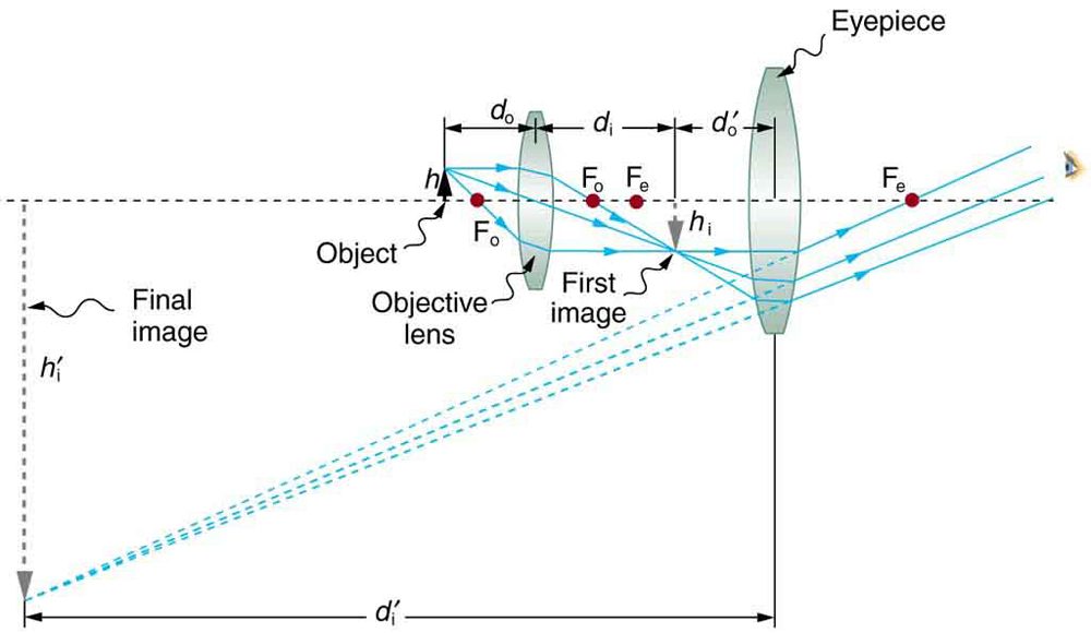
To see how the microscope in Figure 26.16 forms an image, we consider its two lenses in succession. The object is slightly farther away from the objective lens than its focal length , producing a case 1 image that is larger than the object. This first image is the object for the second lens, or eyepiece. The eyepiece is intentionally located so it can further magnify the image. The eyepiece is placed so that the first image is closer to it than its focal length . Thus the eyepiece acts as a magnifying glass, and the final image is made even larger. The final image remains inverted, but it is farther from the observer, making it easy to view (the eye is most relaxed when viewing distant objects and normally cannot focus closer than 25 cm). Since each lens produces a magnification that multiplies the height of the image, it is apparent that the overall magnification is the product of the individual magnifications:
where is the magnification of the objective and is the magnification of the eyepiece. This equation can be generalized for any combination of thin lenses and mirrors that obey the thin lens equations.
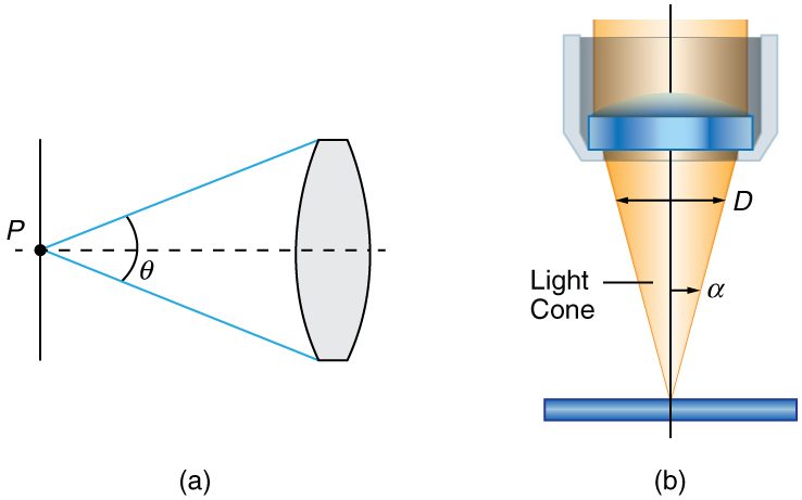
Normal optical microscopes can magnify up to with a theoretical resolution of . The lenses can be quite complicated and are composed of multiple elements to reduce aberrations. Microscope objective lenses are particularly important as they primarily gather light from the specimen. Three parameters describe microscope objectives: the numerical aperture , the magnification , and the working distance. The is related to the light gathering ability of a lens and is obtained using the angle of acceptance formed by the maximum cone of rays focusing on the specimen (see Figure 26.17(a)) and is given by
where is the refractive index of the medium between the lens and the specimen and . As the angle of acceptance given by increases, becomes larger and more light is gathered from a smaller focal region giving higher resolution. A objective gives more detail than a objective.
While the numerical aperture can be used to compare resolutions of various objectives, it does not indicate how far the lens could be from the specimen. This is specified by the “working distance,” which is the distance (in mm usually) from the front lens element of the objective to the specimen, or cover glass. The higher the the closer the lens will be to the specimen and the more chances there are of breaking the cover slip and damaging both the specimen and the lens. The focal length of an objective lens is different than the working distance. This is because objective lenses are made of a combination of lenses and the focal length is measured from inside the barrel. The working distance is a parameter that microscopists can use more readily as it is measured from the outermost lens. The working distance decreases as the and magnification both increase.
The term in general is called the -number and is used to denote the light per unit area reaching the image plane. In photography, an image of an object at infinity is formed at the focal point and the -number is given by the ratio of the focal length of the lens and the diameter of the aperture controlling the light into the lens (see Figure 26.17(b)). If the acceptance angle is small the of the lens can also be used as given below.
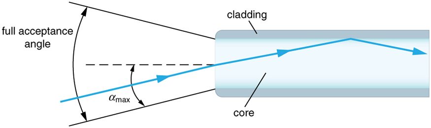
As the -number decreases, the camera is able to gather light from a larger angle, giving wide-angle photography. As usual there is a trade-off. A greater means less light reaches the image plane. A setting of usually allows one to take pictures in bright sunlight as the aperture diameter is small. In optical fibers, light needs to be focused into the fiber. Figure 26.18 shows the angle used in calculating the of an optical fiber.
Can the be larger than 1.00? The answer is ‘yes’ if we use immersion lenses in which a medium such as oil, glycerine or water is placed between the objective and the microscope cover slip. This minimizes the mismatch in refractive indices as light rays go through different media, generally providing a greater light-gathering ability and an increase in resolution. Figure 26.19 shows light rays when using air and immersion lenses.
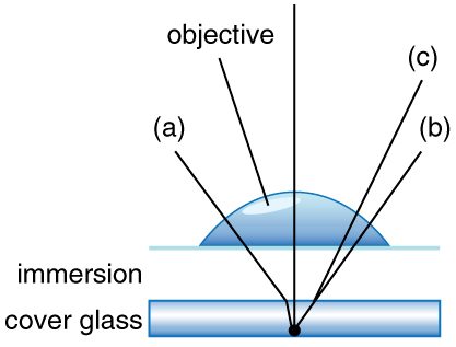
When using a microscope we do not see the entire extent of the sample. Depending on the eyepiece and objective lens we see a restricted region which we say is the field of view. The objective is then manipulated in two-dimensions above the sample to view other regions of the sample. Electronic scanning of either the objective or the sample is used in scanning microscopy. The image formed at each point during the scanning is combined using a computer to generate an image of a larger region of the sample at a selected magnification.
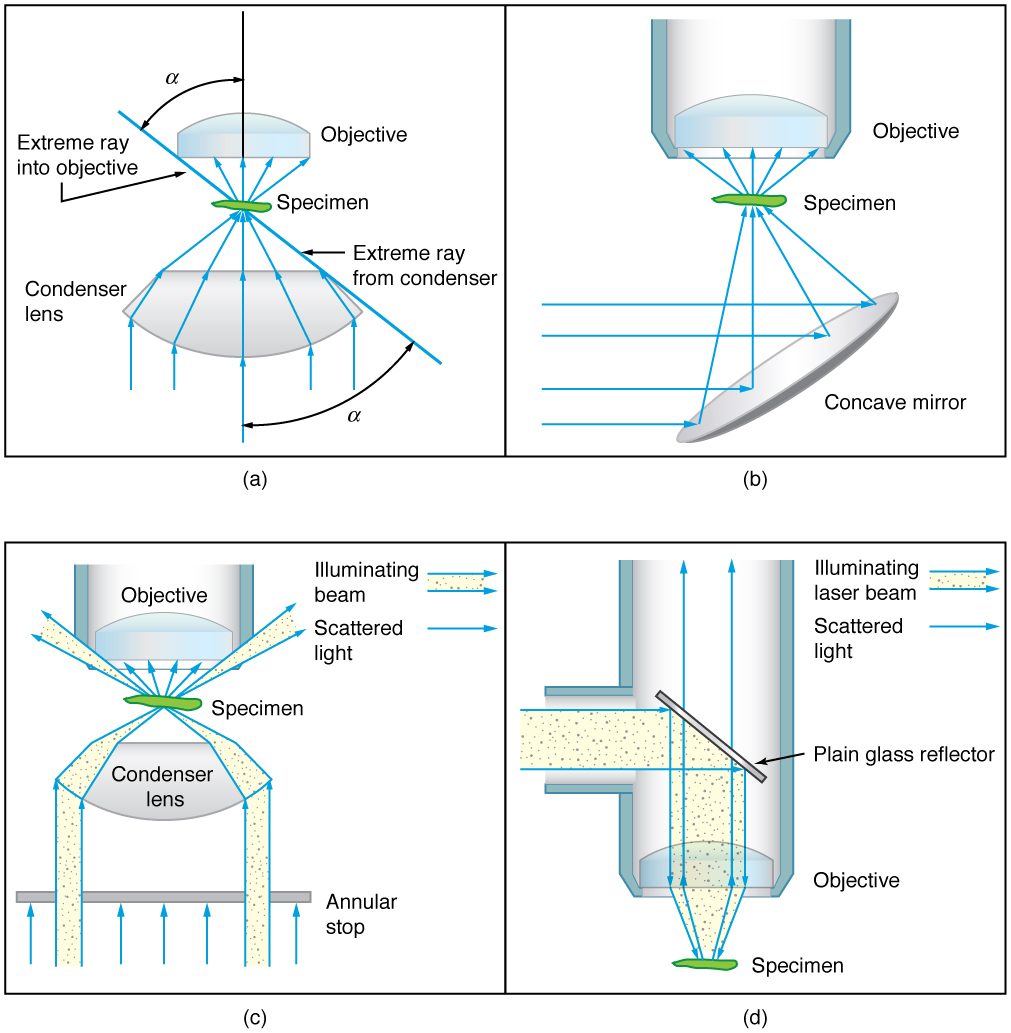
When using a microscope, we rely on gathering light to form an image. Hence most specimens need to be illuminated, particularly at higher magnifications, when observing details that are so small that they reflect only small amounts of light. To make such objects easily visible, the intensity of light falling on them needs to be increased. Special illuminating systems called condensers are used for this purpose. The type of condenser that is suitable for an application depends on how the specimen is examined, whether by transmission, scattering or reflecting. See Figure 26.20 for an example of each. White light sources are common and lasers are often used. Laser light illumination tends to be quite intense and it is important to ensure that the light does not result in the degradation of the specimen.
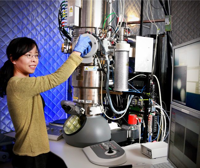
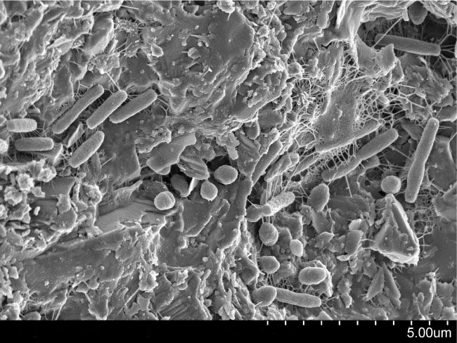
We normally associate microscopes with visible light, but x ray and electron microscopes provide greater resolution. The focusing and basic physics is the same as that just described, even though the lenses require different technology. The electron microscope requires vacuum chambers so that the electrons can proceed unheeded. Magnifications of 50 million times provide the ability to determine positions of individual atoms within materials. An electron microscope is shown in Figure 26.21. We do not use our eyes to form images; rather images are recorded electronically and displayed on computers. In fact observing and saving images formed by optical microscopes on computers is now done routinely. Video recordings of what occurs in a microscope can be made for viewing by many people at later dates. Advances in this powerful technology continue. In the 1990s, Pratibha L. Gai invented the environmental transmission electron microscope (ETEM), which was the first device capable of observing individual atoms in chemical reactions.
Test Prep for AP Courses
Which of the following correctly describes the image created by a microscope?
- The image is real, inverted, and magnified.
- The image is virtual, inverted, and magnified.
- The image is real, upright, and magnified.
- The image is virtual, upright, and magnified.
(b)
Use the diagram shown below to answer the following questions.
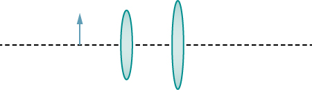
Draw two rays leaving the arrow shown to the left of both lenses. Use ray tracing to draw the images created by the objective and eyepiece lenses. Label the images as io and ie.
Section Summary
- The microscope is a multiple-element system having more than a single lens or mirror.
- Many optical devices contain more than a single lens or mirror. These are analysed by considering each element sequentially. The image formed by the first is the object for the second, and so on. The same ray tracing and thin lens techniques apply to each lens element.
- The overall magnification of a multiple-element system is the product of the magnifications of its individual elements. For a two-element system with an objective and an eyepiece, this is where is the magnification of the objective and is the magnification of the eyepiece, such as for a microscope.
- Microscopes are instruments for allowing us to see detail we would not be able to see with the unaided eye and consist of a range of components.
- The eyepiece and objective contribute to the magnification. The numerical aperture of an objective is given by where is the refractive index and the angle of acceptance.
- Immersion techniques are often used to improve the light gathering ability of microscopes. The specimen is illuminated by transmitted, scattered or reflected light though a condenser.
- The describes the light gathering ability of a lens. It is given by
Conceptual Questions
Geometric optics describes the interaction of light with macroscopic objects. Why, then, is it correct to use geometric optics to analyse a microscope’s image?
The image produced by the microscope in Figure 26.16 cannot be projected. Could extra lenses or mirrors project it? Explain.
Why not have the objective of a microscope form a case 2 image with a large magnification? (Hint: Consider the location of that image and the difficulty that would pose for using the eyepiece as a magnifier.)
What advantages do oil immersion objectives offer?
How does the of a microscope compare with the of an optical fiber?
Problem Exercises
A microscope with an overall magnification of 800 has an objective that magnifies by 200. (a) What is the magnification of the eyepiece? (b) If there are two other objectives that can be used, having magnifications of 100 and 400, what other total magnifications are possible?
(a) 4.00
(b) 1600
(a) What magnification is produced by a 0.150 cm focal length microscope objective that is 0.155 cm from the object being viewed? (b) What is the overall magnification if an eyepiece (one that produces a magnification of 8.00) is used?
(a) Where does an object need to be placed relative to a microscope for its 0.500 cm focal length objective to produce a magnification of ? (b) Where should the 5.00 cm focal length eyepiece be placed to produce a further fourfold (4.00) magnification? (c) Is this a realistic design for a microscope?
(a) 0.501 cm
(b) Eyepiece should be 204 cm behind the objective lens.
(c) No, a distance of 205 cm (which is over 2 m) is unrealistic for the tube of a microscope.
You switch from a oil immersion objective to a oil immersion objective. What are the acceptance angles for each? Compare and comment on the values. Which would you use first to locate the target area on your specimen?
An amoeba is 0.305 cm away from the 0.300 cm focal length objective lens of a microscope. (a) Where is the image formed by the objective lens? (b) What is this image’s magnification? (c) An eyepiece with a 2.00 cm focal length is placed 20.0 cm from the objective. Where is the final image? (d) What magnification is produced by the eyepiece? (e) What is the overall magnification? (See Figure 26.16.)
(a) +18.3 cm (on the eyepiece side of the objective lens)
(b) -60.0
(c) -11.3 cm (on the objective side of the eyepiece)
(d) +6.67
(e) -400
You are using a standard microscope with a objective and switch to a objective. What are the acceptance angles for each? Compare and comment on the values. Which would you use first to locate the target area on of your specimen? (See Figure 26.17.)
Unreasonable Results
Your friends show you an image through a microscope. They tell you that the microscope has an objective with a 0.500 cm focal length and an eyepiece with a 5.00 cm focal length. The resulting overall magnification is 250,000. Are these viable values for a microscope?
Adapted from College Physics 2e by OpenStax (openstax.org), licensed under CC BY-NC-SA 4.0. Changes were made. License: CC-BY-NC-SA-4.0.