
24.2 Production of Electromagnetic Waves
Learning Objectives
By the end of this section, you will be able to:
- Describe the electric and magnetic waves as they move out from a source, such as an AC generator.
- Explain the mathematical relationship between the magnetic field strength and the electrical field strength.
- Calculate the maximum strength of the magnetic field in an electromagnetic wave, given the maximum electric field strength.
We can get a good understanding of electromagnetic waves (EM) by considering how they are produced. Whenever a current varies, associated electric and magnetic fields vary, moving out from the source like waves. Perhaps the easiest situation to visualize is a varying current in a long straight wire, produced by an AC generator at its center, as illustrated in Figure 24.5.
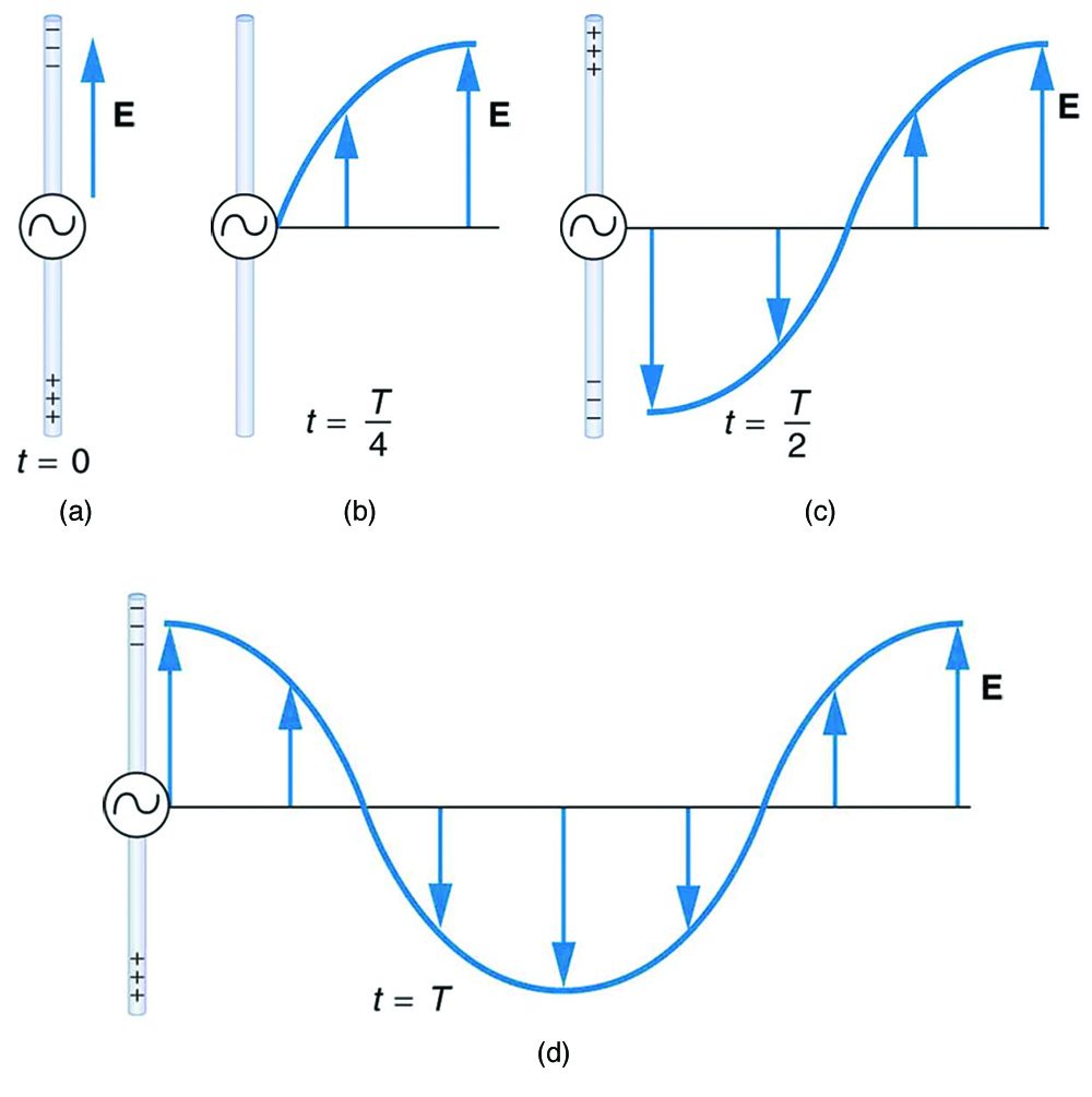
The electric field () shown surrounding the wire is produced by the charge distribution on the wire. Both the and the charge distribution vary as the current changes. The changing field propagates outward at the speed of light.
There is an associated magnetic field () which propagates outward as well (see Figure 24.6). The electric and magnetic fields are closely related and propagate as an electromagnetic wave. This is what happens in broadcast antennae such as those in radio and TV stations.
Closer examination of the one complete cycle shown in Figure 24.5 reveals the periodic nature of the generator-driven charges oscillating up and down in the antenna and the electric field produced. At time , there is the maximum separation of charge, with negative charges at the top and positive charges at the bottom, producing the maximum magnitude of the electric field (or -field) in the upward direction. One-fourth of a cycle later, there is no charge separation and the field next to the antenna is zero, while the maximum -field has moved away at speed .
As the process continues, the charge separation reverses and the field reaches its maximum downward value, returns to zero, and rises to its maximum upward value at the end of one complete cycle. The outgoing wave has an amplitude proportional to the maximum separation of charge. Its wavelength is proportional to the period of the oscillation and, hence, is smaller for short periods or high frequencies. (As usual, wavelength and frequency are inversely proportional.)
Electric and Magnetic Waves: Moving Together
Following Ampere’s law, current in the antenna produces a magnetic field, as shown in Figure 24.6. The relationship between and is shown at one instant in Figure 24.6 (a). As the current varies, the magnetic field varies in magnitude and direction.
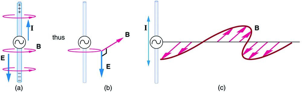
The magnetic field lines also propagate away from the antenna at the speed of light, forming the other part of the electromagnetic wave, as seen in Figure 24.6 (b). The magnetic part of the wave has the same period and wavelength as the electric part, since they are both produced by the same movement and separation of charges in the antenna.
The electric and magnetic waves are shown together at one instant in time in Figure 24.7. The electric and magnetic fields produced by a long straight wire antenna are exactly in phase. Note that they are perpendicular to one another and to the direction of propagation, making this a transverse wave.
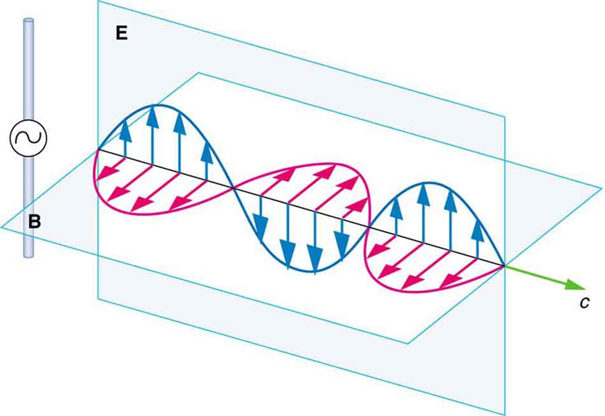
Electromagnetic waves generally propagate out from a source in all directions, sometimes forming a complex radiation pattern. A linear antenna like this one will not radiate parallel to its length, for example. The wave is shown in one direction from the antenna in Figure 24.7 to illustrate its basic characteristics.
Instead of the AC generator, the antenna can also be driven by an AC circuit. In fact, charges radiate whenever they are accelerated. But while a current in a circuit needs a complete path, an antenna has a varying charge distribution forming a standing wave, driven by the AC. The dimensions of the antenna are critical for determining the frequency of the radiated electromagnetic waves. This is a resonant phenomenon and when we tune radios or TV, we vary electrical properties to achieve appropriate resonant conditions in the antenna.
Receiving Electromagnetic Waves
Electromagnetic waves carry energy away from their source, similar to a sound wave carrying energy away from a standing wave on a guitar string. An antenna for receiving EM signals works in reverse. And like antennas that produce EM waves, receiver antennas are specially designed to resonate at particular frequencies.
An incoming electromagnetic wave accelerates electrons in the antenna, setting up a standing wave. If the radio or TV is switched on, electrical components pick up and amplify the signal formed by the accelerating electrons. The signal is then converted to audio and/or video format. Sometimes big receiver dishes are used to focus the signal onto an antenna.
In fact, charges radiate whenever they are accelerated. When designing circuits, we often assume that energy does not quickly escape AC circuits, and mostly this is true. A broadcast antenna is specially designed to enhance the rate of electromagnetic radiation, and shielding is necessary to keep the radiation close to zero. Some familiar phenomena are based on the production of electromagnetic waves by varying currents. Your microwave oven, for example, sends electromagnetic waves, called microwaves, from a concealed antenna that has an oscillating current imposed on it.
Relating -Field and -Field Strengths
There is a relationship between the - and -field strengths in an electromagnetic wave. This can be understood by again considering the antenna just described. The stronger the -field created by a separation of charge, the greater the current and, hence, the greater the -field created.
Since current is directly proportional to voltage (Ohm’s law) and voltage is directly proportional to -field strength, the two should be directly proportional. It can be shown that the magnitudes of the fields do have a constant ratio, equal to the speed of light. That is,
is the ratio of -field strength to -field strength in any electromagnetic wave traveling in a vacuum. This is true at all times and at all locations in space, a simple and elegant result.
An electromagnetic wave traveling in a medium, with index of refraction n, will propagate at a lower speed,
The ratio of the field strengths will be similarly reduced, such that in the medium,
The result of this example is consistent with the statement made in the module Maxwell’s Equations: Electromagnetic Waves Predicted and Observed that changing electric fields create relatively weak magnetic fields. They can be detected in electromagnetic waves, however, by taking advantage of the phenomenon of resonance, as Hertz did. A system with the same natural frequency as the electromagnetic wave can be made to oscillate. All radio and TV receivers use this principle to pick up and then amplify weak electromagnetic waves, while rejecting all others not at their resonant frequency.
Test Prep for AP Courses
If an electromagnetic wave is described as having a frequency of 3 GHz, what are its period and wavelength (in a vacuum)?
- 3.0 × 10⁹s, 10 cm
- 3.3 × 10⁻¹⁰s, 10 cm
- 3.3 × 10⁻¹⁰s, 10 m
- 3.0 × 10⁹s, 10 m
(b)
Describe the outcome if you attempt to produce a longitudinal electromagnetic wave.
A wave is travelling through a medium until it hits the end of the medium and there is nothing but vacuum beyond. What happens to a mechanical wave? Electromagnetic wave?
- reflects backward, continues on
- reflects backward, reflects backward
- continues on, continues on
- stops, continues on
(a)
You’re on the moon, skipping around, and your radio breaks. What would be the best way to communicate this problem to your friend, who is also skipping around on the moon: yelling or flashing a light? Why?
Given the waveform in Figure 24.5(d), if
and
,
which of the following is the correct equation
for the wave at the antenna?
(d)
Given the waveform in Figure 24.5(d), if GHz and , what is the correct equation for the magnetic field wave at the antenna?
In Heinrich Hertz’s spark gap experiment (Figure 24.4), how will the induced sparks in Loop 2 compare to those created in Loop 1?
- Stronger
- Weaker
- Need to know the tuner settings to tell
- Weaker, but how much depends on the tuner settings.
(d)
The sun is far away from the Earth, and the intervening space is very close to empty. Yet the tilt of the Earth’s axis of rotation relative to the sun results in seasons. Explain why, given what you have learned in this section.
Section Summary
- Electromagnetic waves are created by oscillating charges (which radiate whenever accelerated) and have the same frequency as the oscillation.
- Since the electric and magnetic fields in most electromagnetic waves are perpendicular to the direction in which the wave moves, it is ordinarily a transverse wave.
- The strengths of the electric and magnetic parts of the wave are related by
which implies that the magnetic field is very weak relative to the electric field .
Conceptual Questions
The direction of the electric field shown in each part of Figure 24.5 is that produced by the charge distribution in the wire. Justify the direction shown in each part, using the Coulomb force law and the definition of , where is a positive test charge.
Is the direction of the magnetic field shown in Figure 24.6 (a) consistent with the right-hand rule for current (RHR-2) in the direction shown in the figure?
Why is the direction of the current shown in each part of Figure 24.6 opposite to the electric field produced by the wire’s charge separation?
In which situation shown in Figure 24.8 will the electromagnetic wave be more successful in inducing a current in the wire? Explain.
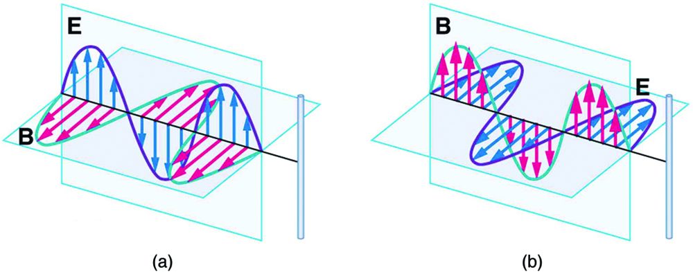
In which situation shown in Figure 24.9 will the electromagnetic wave be more successful in inducing a current in the loop? Explain.
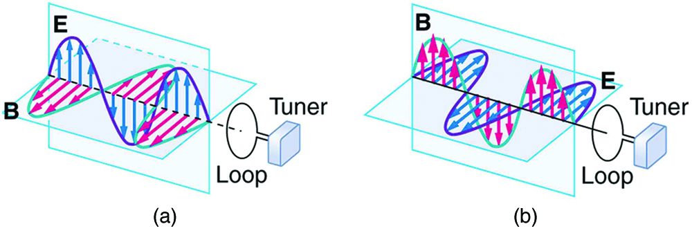
Should the straight wire antenna of a radio be vertical or horizontal to best receive radio waves broadcast by a vertical transmitter antenna? How should a loop antenna be aligned to best receive the signals? (Note that the direction of the loop that produces the best reception can be used to determine the location of the source. It is used for that purpose in tracking tagged animals in nature studies, for example.)
Under what conditions might wires in a DC circuit emit electromagnetic waves?
Give an example of interference of electromagnetic waves.
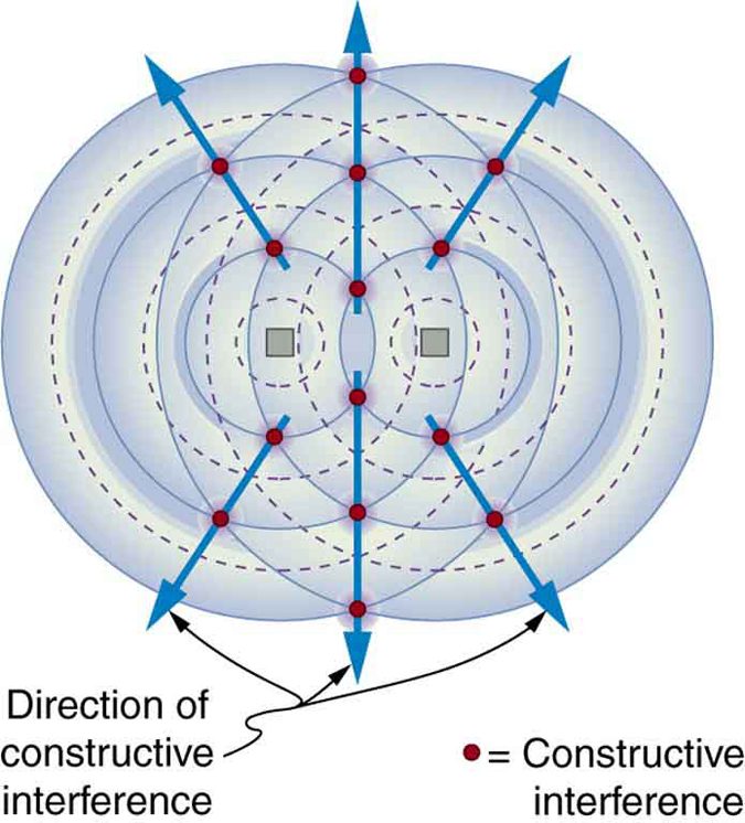
Figure 24.10 shows the interference pattern of two radio antennas broadcasting the same signal. Explain how this is analogous to the interference pattern for sound produced by two speakers. Could this be used to make a directional antenna system that broadcasts preferentially in certain directions? Explain.
Can an antenna be any length? Explain your answer.
Problems & Exercises
What is the maximum electric field strength in an electromagnetic wave that has a maximum magnetic field strength of (about 10 times the Earth’s)?
150 kV/m
The maximum magnetic field strength of an electromagnetic field is . Calculate the maximum electric field strength if the wave is traveling in a medium in which the speed of the wave is .
Verify the units obtained for magnetic field strength in Example 1 (using the equation ) are in fact teslas (T).
Adapted from College Physics 2e by OpenStax (openstax.org), licensed under CC BY-NC-SA 4.0. Changes were made. License: CC-BY-NC-SA-4.0.